[Blog list(Japanese)]
● Blog top page
[External pages(Japanese)]
● Home Recording Song Collection
● DIY guitar effect pedals/tools/parts
● Small-sized N gauge miniature model railway
● Blog top page
[External pages(Japanese)]
● Home Recording Song Collection
● DIY guitar effect pedals/tools/parts
● Small-sized N gauge miniature model railway
A3-Size N-Scale Model Railway: Automated Operation System with Touch-Panel TFT Display
2025/09/07
Change language: 日本語
From the First Version with LCD Character Display
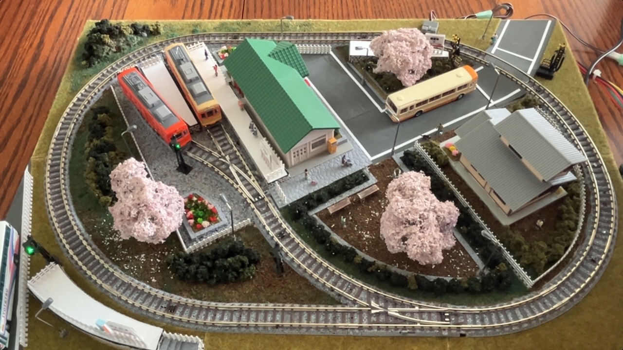
About 45 years ago, when I was a junior and senior high school student living in Matsuyama, I created an A3-size model railway layout inspired by the Iyo Railway. I still enjoy running trains on this diorama today, but I wanted to try automated operation, so I built a control system using Arduino.
The first version used a simple LCD character display as the user interface. Although its display functions were limited, it enabled automated train control. This system was also showcased on YouTube:
Toward a Smarter UI — Introducing the TFT Touch Display
To create a more intuitive interface, I turned my attention to a low-cost (~¥1,000) TFT color LCD module with a touch panel sold by Akizuki Denshi Tsusho. It supports SPI communication.
I thought:
"If I use this, I could draw the layout map directly on the screen and visualize the running state and automatic operation in a graphical way."
This led me to build a new controller using the TFT display.
Hardware Structure
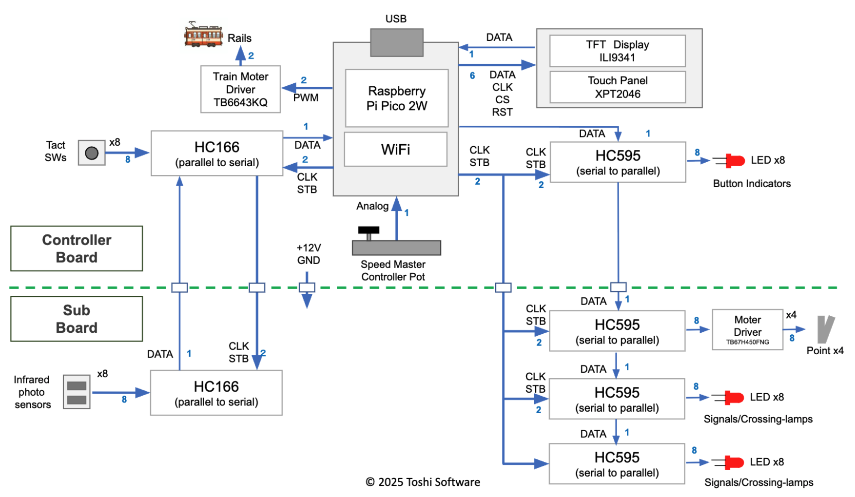
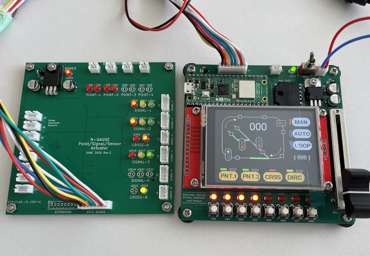
The system is composed of two boards:
- Controller board: Equipped with a TFT display and microcontroller (Raspberry Pi Pico 2W)
- Sub board: Installed under the layout, connecting multiple devices such as turnouts and signals
The two boards are linked with an 8-pin connector. The sub board includes shift register ICs, allowing control of many I/Os via serial communication.
PCB Design — Using KiCAD and JLCPCB
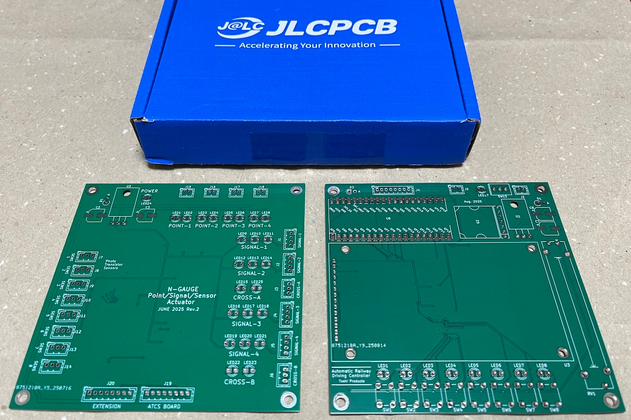
I designed two types of boards in KiCAD and had them fabricated by JLCPCB in China:
- Controller board (TFT + microcontroller)
- Sub board (shift register ICs)
Both boards are 2-layer SMD designs using chip components.。
Circuit diagrams and KiCAD data are available on GitHub:
Layout Structure
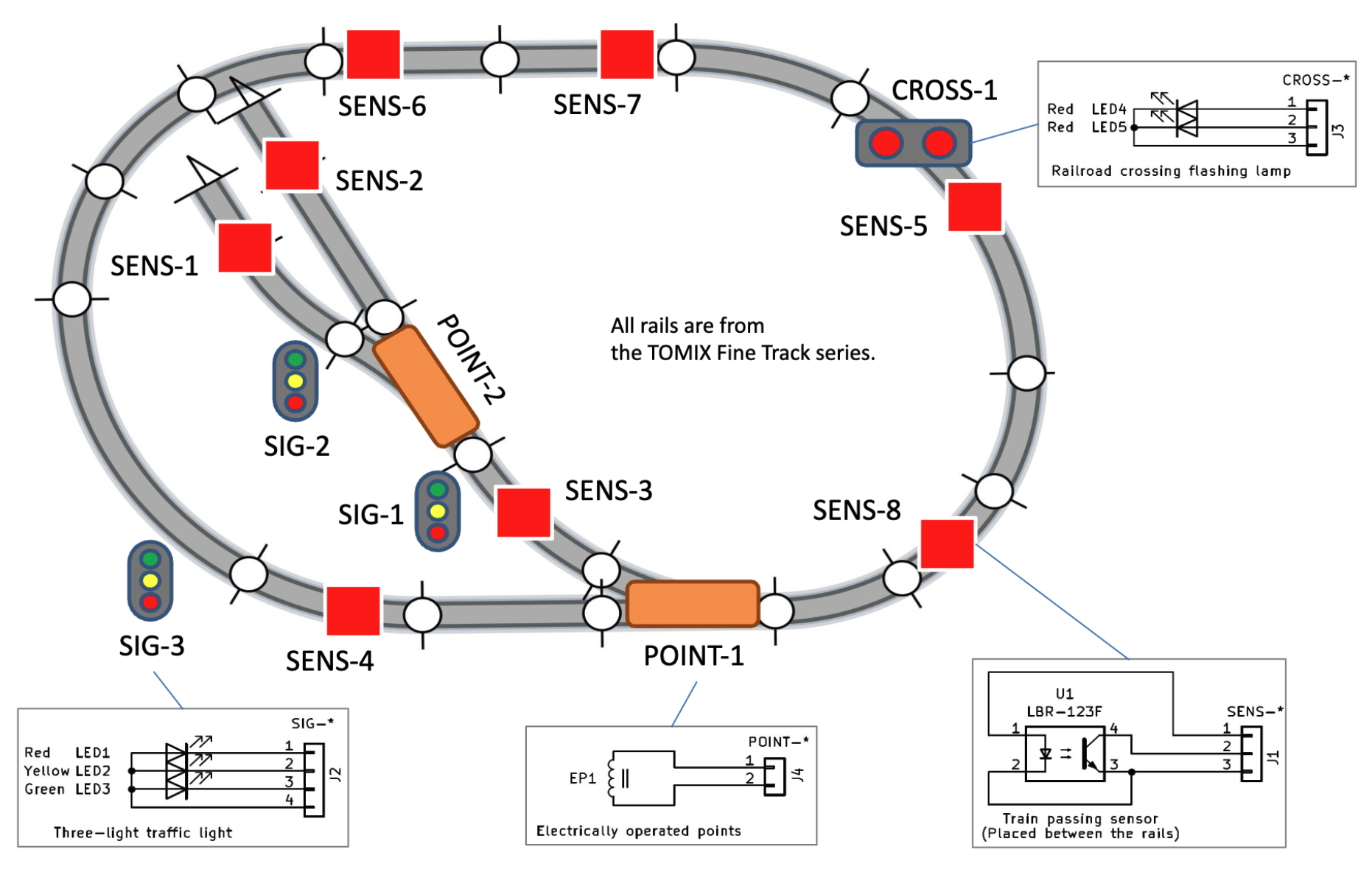
The layout includes the following elements:
Turnouts (POINT) — TOMIX N-PL140-30
3-light signal (SIG) — Scenery Collection Traffic Signal Light
Level crossing warning lamp (CROSS) — Production blog page
Infrared sensors (SENS) — Production blog page
Originally, I used magnetic sensors to detect train passage, but the magnets interfered with the turnout mechanisms. I replaced them with reflective infrared sensors.
All devices are connected to the sub board under the layout for centralized control.
Software Design
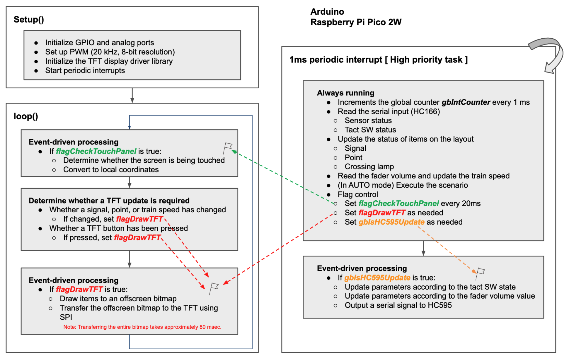
The software was written using Arduino IDE. Since the TFT display is controlled via SPI, a full-screen redraw takes about 80 ms. If all processes were placed inside loop(), sensor inputs could be missed during screen updates.
To avoid this, I designed the program as follows:
- Only the TFT drawing process is placed in loop()
- Sensor and signal control are handled via interrupts
This ensures that even during display updates, high-priority operations run immediately and the system remains responsive.
Source code is available here:
Verifying Interrupt Timing
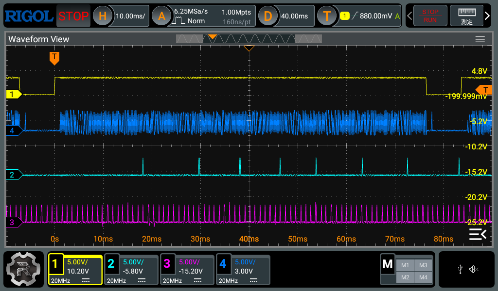
To confirm that interrupts executed correctly, I measured waveforms with an oscilloscope. By setting GPIO HIGH at the start of each transfer function and LOW at the end, I could measure execution times.
Signal assignments:
- [1]Yellow — HIGH during SPI transfer to TFT
- [4]Blue — SCK clock to TFT during transfer
- [2]Green — HIGH during serial transfer to HC595 (output shift register)
- [3]Red — HIGH during serial transfer to HC166 (input shift register)
The measurements showed that even during SPI transfers to the TFT, 1 ms interrupts for HC595 and HC166 transfers executed reliably.
Measuring Serial Transfer Time
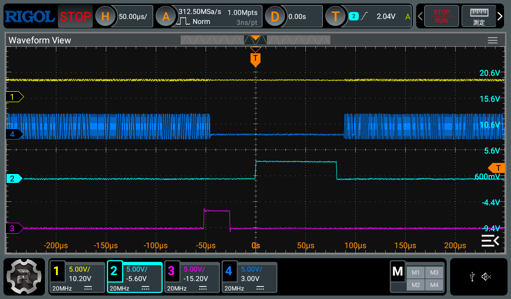
Zooming in on the same signals, I measured the duration of serial transfers:
- [2]Green: HC595 (output) transfer: ~70 μs
- [3]Red: HC166 (input) transfer: ~25 μs
Both fit comfortably within the 1 ms interrupt cycle, confirming stable operation.
Results and Considerations
The measurements proved that even while updating the TFT display, sensor input and layout control were executed consistently at the intended cycle and timing.
This validates the reliability of the automated control system.
Build Log
The build process is documented across several blog posts:
You can also view all related posts under the “Model Railway” category.
Operation Demo (YouTube)
The full system overview and automatic operation demo are presented in these YouTube videos (with commentary, ~7 minutes each).
Other blogs
[NOTE] For Japanese pages, please use your browser's translation function.
2025/09/07 09:41
| Blog list
© 2025 Toshi Software

