Self-made BOSS Octaver OC-2 MOD using CMOS flip-flop
Self-made Guitar Effect Pedals
Explore the articles to learn more about your favorite effect pedals.
|
Analog octaver BOSS CE-2
An octave is a effect pedal that generates a sound one or two octaves lower than the original sound and easily reproduces an octave playing style like Wes Montgomery. The current BOSS latest model OC-3 is composed of digital circuits and can be used with chords with multiple notes. This is DSP processed and cannot be made by myself. I am a self-made nerd. Even though I already have an OC-3, I tried to make an analog version.
Circuits and key components
The schematic of BOSS OC-2 can be found in the service manual for repairs. No special part is used, but it contains parts (ICs) that are no longer available because it was released in 1982.
Two CMOS flip-flops are used. One is the CD4013, which can be obtained anywhere. The other is a ROHM BA634 chip. This is an IC with one circuit of ordinary flip-flops and not generally available. Therefore, it is necessary to replace this flip-flop with another CMOS IC.
When I was browsing the internet, there was a person who made OC-2 experimentally. The circuit diagram was also posted, so I referred to it and entered it in the circuit diagram software. The JK flip-flop CD4027 is used as an alternative to the BA634.
Circuit mistakes
When I made the board and checked the operation, I discovered that the circuit that I referred to contained two mistakes. One is that the polarity of the input electrolytic capacitor C2 is reversed, and the other is that the 7th pin (must be "L (GND)") of the replaced CD4027 is connected to wrong VDD (+ 9V). I fixed it by cutting the trace on the printed circuit board and reconnecting it.
Principle of operation (observing the waveform)
The operating principle of the octaver is: First, the high frequency range of the input sound is cut with a low-pass filter to create a square wave with the pitch (frequency) of the original sound. At this time, the actual circuit is devised so that a stable pitch waveform (square wave) can be obtained by applying a peak hold circuit. This pitch waveform is divided into 1/2 and 1/4 using a CMOS flip-flop to create a pitch signal one or two octaves lower.
These pitch signals and the input tones half-wave rectified by the germanium diode are multiplied by the op amp's circuit. As a result, the half-wave rectified tone is inverted every other wave and converted into a signal with twice the wavelength. This is a clever circuit that replaces the pitch of the input sound with the sound one octave lower.
Designed a two-layer printed circuit board ordered from "Fusion PCB"
This time, I designed the printed circuit board by myself as well as the previous analog delay self-made (DM-3 MOD). I placed an order with "Fusion PCB" in Shenzhen, China, who produces 10 PCBs for $ 5. The board design was done using the freeware "KiCAD" for all processes.
The manufacturing fee is only $ 5, but the shipping fee by DHL is $ 20, so the total is $ 25. This is still cheap enough.
When ordering with FusionPCB, you can select the resist color (green, red, blue, etc.), but this color selection seems to affect the delivery date. I think it depends on the manufacturing situation of the factory at that time, but the most common color "green" is delivered fastest. Once I chose "red" when creating an analog delay, the delivery time was longer, 12 business days from ordering to completion of production. Since I chose "green" this time, it took 5 business days from ordering to completion of production. DHL delivery took other 5 business days.
PCB design with KiCAD
All processes of PCB design can be done with the freeware "KiCAD". I used KiCAD Ver.5.19. It can be created only with the parts library provided by default. The trace design is fairly easy since the two-layer board can draw trace on the front and back. I connect all the lines except GND, and filled all the remaining GND with solid earth.
The board size was decided to be 60mm wide according to the enclosure "HAMMOND 1590N1" width inside. I shortened the length of PCB while placing the parts, and finally it was 90 mm.
Board design requires some experience (I worked for an electronics design company about 25 years ago). There are many books on CAD and board design methods, so you can refer to them and make your own.
KiCad PCB design data
The PCB data created using "KiCad (Windows 64-bit) Version: (6.0.4), release build" is provided. The ZIP file contains the schematic, board design data, and original component data. Please read the terms of use and disclaimer in the attached "readme.pdf" before using this data.
Obtaining parts
The main parts CD4013 and CD4027 are available everywhere. Regarding the transistor for small signals, "2SC732" was used for the original OC-2, but it was difficult to obtain, so I used the alternative "2N3904". "2SC1815" can also be used.
In addition, "2SK30A-Y" is used for FET. This is also not manufactured and difficult to obtain, but I was lucky enough to buy it. If you can't get it, "2SK2880" can be used instead.
Others are ordinary electronic components. The resistors are 1/4W 5% carbon, the capacitors is cheap box type or ceramic type, and the electrolytic capacitors are also the cheapest.

Main components CMOS CD4013, CD4027, rare operational amplifier LM324
Component mounting and soldering
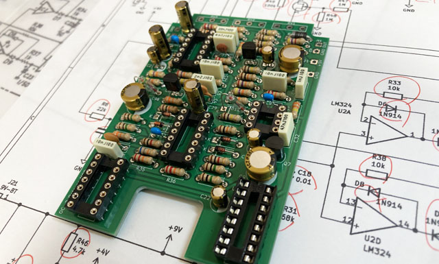
I put the purchased parts on the PCB. For me as a self-made nerd, soldering parts is the most enjoyable task. This fun work was completed in about two hours.
Operation check and noise suppression
Noise generated in direct sound
There is no adjustment on this board. I checked the operation and tried playing with a guitar. The octave sound comes out as expected, but the direct sound (original sound) has a little jarring noise. Apparently, the pitch signal (square wave) divided by CMOS was added on the direct sound.
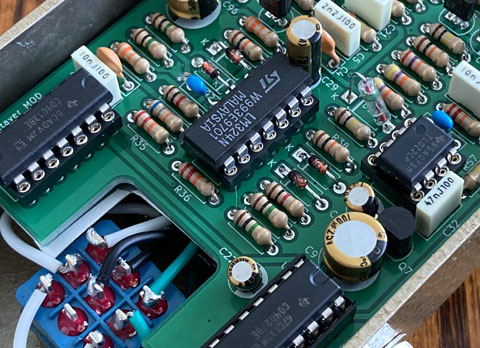
Around the frequency divider circuit that creates the pitch signal
In order to suppress the noise, I tried to wire the power supply of the input operational amplifier (TL074) directly to the power supply input and increase the bypass capacitor, but it had no effect. Also, I tried to add a 330p capacitor to the pitch signal output from CMOS to remove the sharp edge of waveform. It was slightly effective, but it did not change much.
I was at a loss for a while, but suddenly I noticed that there was no noise when I tried playing guitar with the board upright in the enclosure. Apparently, noise jumps from around the CMOS on the board to the pots and jacks inside the enclosure when the board is housed in the enclosure.
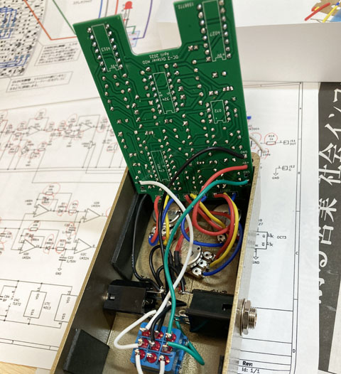
No noise occured when the board was upright in the enclosure
Noise suppression with shield sheet
Therefore, I made a shield plate using aluminum foil tape. I cut a thin transparent plastic sheet into the shape of a board, and attached the aluminum foil tape (double-sided conductive) that I used to make the Stratocaster's pickguard shield. For shielding, I put it under the CMOS chip and the operational amplifier LM324. The effect was great, and no noise was added even if the board was housed in the enclosure.
However, this shield sheet may not be necessary depending on the size of the enclosure and the mounting method of the PCB. You may decide to add a shield sheet after checking the noise level with mounting in the enclosure.
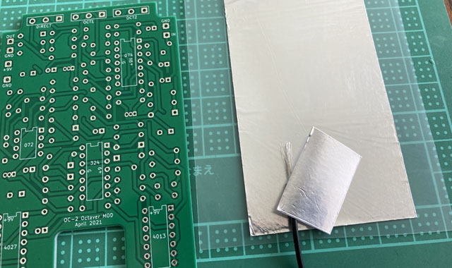
Self-made shield sheet
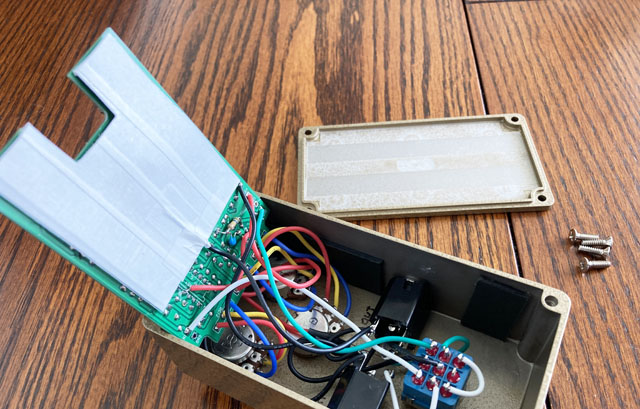
A shield sheet attached to the back side of the board (insulated with paper tape)
Built into the enclosure
Enclosure processing
I housed this ovtaver in a gold-painted enclosure of HAMONND's "1590N1". I call it "Gold Octaver".
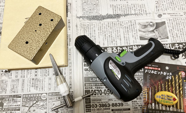
The enclosure was processed using a hand drill. After positioning, the holes were expanded in the order of 1.5mm, 3mm, and 6mm, and then expanded to the hole diameter of each part using a taper reamer.
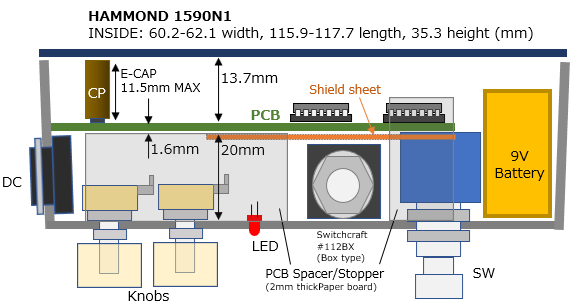
Placement image in the enclosure
I designed the component placement so that the phone jack and foot switch do not interfere with the PCB. In addition, the position of the switch was decided so that the battery space could be taken. The small Switchcraft box-type phone jack (# 112BX) can be used.
I made a 3mm hole and pushed the LED from the inside and fixed it with super glue. I don't use the uncool LED holder. If you want to make it in the same way, please refer to the figure below.
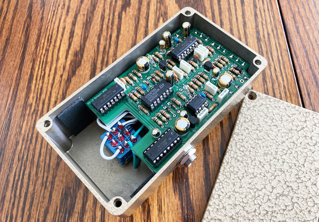
Inside of the beautifully finished gold octaver (battery snap removed)
Sound sample
It's a phrase of my composition "Mico's Dance". It sounds like an octave playing, but I actually play single notes through this pedal.
Recoeding environment:
Gibson Les Paul(Front hum) -> Self-made Noise Reduction -> Self-made Keeley Comp Direct Mix -> Self-made Analog Octaver -> Self-made Cabinet simulator -> UR22mkII -> DAW(Studio One)
![]() Sample: Octave playing-ish sample (MP3)
Sample: Octave playing-ish sample (MP3)
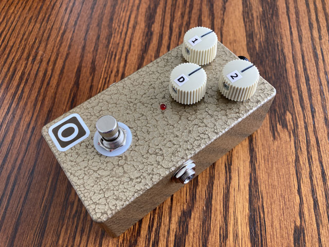
The finished gold octaver. Beautiful!
What I felt after making the octaver
In the first place, if you just want to add the sound one octave lower, I think that the pitch shifter that changes the pitch digitally is more stable. The BOSS OC-3, which I've been using for a while, also supports polyphonic code with digital processing. However, the octave sound was heard separately from the original string sound, which made me feel uncomfortable. I guess it's because there is a delay in the octave sound.
This time, I actually made it using the circuit of OC-2. I think the person who first devised this circuit was probably an analog master. When I analyzed the operation of the circuit myself, I was impressed by the ingenuity of producing a stable sound one octave lower with only the analog circuit.
In actual octave playing, I think it's normal to play with a downstroke. In this case, the thicker string (one octave lower) sounds first, followed by the thinner string. If you use a digital pitch shifter, there will always be a delay to change the pitch, and if you play a single note on a thin string, the result will be an octave lower pitched note later. Therefore, I don't think it will ever sound like an actual octave playing.
The analog octaver does not delay the sound one octave lower, but the sound is generated simultaneously at the waveform level. For this reason, I think that it becomes close to the octave playing.
The principle of the analog octaver is like a Hammond organ of the good old days that makes a sound by turning a gear (called a tone wheel). It's a primitive mechanism, but it's still smart and complete.
For those who want to make their own effect pedal from now on, I made a page explaining how to select a tool. Please refer to it.
Language
Self-made
effect pedals
- Pedals list page
 Self-made pedals tool selection
VEMURAM Jan Ray
Xotic BB preamp
Klon Centaur
 Revived old YAHAMA Chorus
 MXR Envelop Filter
 BBD Analg Delay DM-3 MOD
 BBD Analg Chorus CE-3 MOD
CMOS Octaver OC-2 MOD
 Riot using surface mount parts
 Original design noise gate
 EP BOOSTER & MICRO AMP duo
 Keeley 4 Knob Comp
 MXR Phase 90 MOD
 Blend Comp based on Keeley
 DM-3 longer delay time MOD
 Noise reduction pedal using VCA V2164


