How to make your own guitar effect pedals, tool selection
Self-made Guitar Effect Pedals
Explore the articles to learn more about your favorite effect pedals.
|
My Guitar Effect Pedal Production Experience
I've been playing guitar for over 45 years, and with more time at home due to COVID-19, I've delved into creating my own effect pedals over the past year. Crafting analog effect pedals has become a passionate hobby for me, allowing me to build customized pedal boards with my creations. Let me share with you the effect pedals I've made and the tools I use for making them.
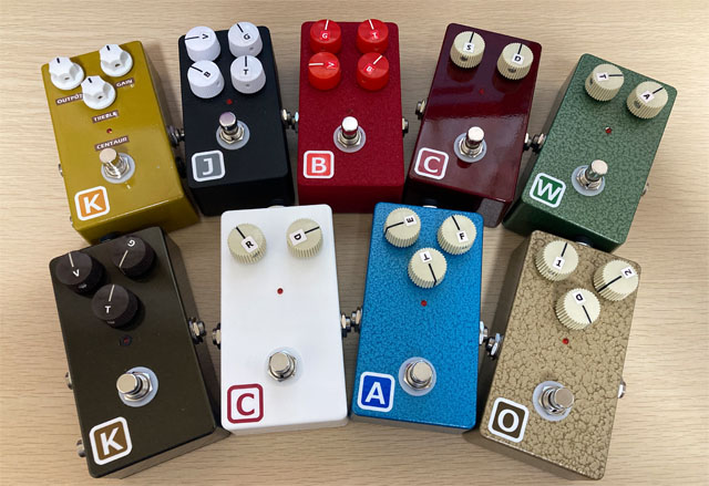
A full lineup of self-made effect pedals
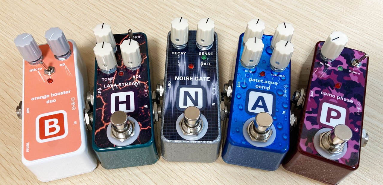
Self-made pedals using surface mount components
How to make your own effect pedals
Gathering Information on Circuits and Board Trace
![]() To create an effect pedal, you need circuit diagram and PCB trace information. While you can wire directly from a circuit diagram onto a universal board or design your own printed circuit board (PCB), these tasks are challenging for beginners without extensive experience. It's highly recommended that newcomers use ready-made PCBs.
To create an effect pedal, you need circuit diagram and PCB trace information. While you can wire directly from a circuit diagram onto a universal board or design your own printed circuit board (PCB), these tasks are challenging for beginners without extensive experience. It's highly recommended that newcomers use ready-made PCBs.
I rely on the following websites to gather information for creating my own effect pedals:
![]() TONEPAD FX PROJECTS is a long-established site founded in 2001, dedicated to the DIY community for effect pedals. It serves as a hub where enthusiasts exchange information and resources. The site features circuit diagrams derived from actual product circuit boards and provides printed circuit board trace diagrams for DIY projects. They also offer printed circuit boards for sale, with international shipping available (according to their FAQ page, shipping worldwide costs $4).
TONEPAD FX PROJECTS is a long-established site founded in 2001, dedicated to the DIY community for effect pedals. It serves as a hub where enthusiasts exchange information and resources. The site features circuit diagrams derived from actual product circuit boards and provides printed circuit board trace diagrams for DIY projects. They also offer printed circuit boards for sale, with international shipping available (according to their FAQ page, shipping worldwide costs $4).
 Effects Layouts is a site dedicated to DIY effector enthusiasts. It features single-sided board layouts of various effectors. The site provides PDF pattern diagrams of printed circuit boards, allowing users to create their own PCBs using photosensitive boards. Additionally, there are image diagrams for hand-wiring with point-to-point on universal boards.
![]() Guitar FX Layouts, established around 2010, focuses on DIY guitar effects. The site features production articles using a special universal board called "stripboard" or "bello board." Stripboard enables users to create traces by cutting horizontal rows with a drill, making circuit assembly easier and more organized compared to manual point-to-point wiring on general universal boards.
Guitar FX Layouts, established around 2010, focuses on DIY guitar effects. The site features production articles using a special universal board called "stripboard" or "bello board." Stripboard enables users to create traces by cutting horizontal rows with a drill, making circuit assembly easier and more organized compared to manual point-to-point wiring on general universal boards.
Easy effect pedal kits
If you're looking to start making your own pedals easily, I recommend using effect pedal kits that come with all the necessary parts. You can find many kits available on Amazon and other platforms. For beginners, I suggest starting with distortion or overdrive pedals, as they are relatively simple to assemble.
About the production of circuit boards
Printed circuit board (PCB)
PCBs can be purchased from internet sites such as "TONEPAD FX PROJECTS" and Amazon. You can easily find them by searching for "(effect pedal name) + PCB" on Google and viewing the image results.
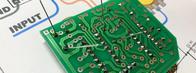
Making with a universal board
You don't have to use a PCB to make an effect pedal. You can also use an inexpensive universal board. However, universal boards can be challenging for beginners, so I recommend trying them out from your second or third project onward.
There are two main types of universal boards commonly used in effect pedal production.
Universal board (dot pattern)
A universal board features holes with a diameter of 0.9-1.0 mm spaced at 2.54 mm intervals, each with independent lands (copper foil). It comes in two main materials: "paper phenol," which is soft and easy to work with, and "glass epoxy," known for its durability. Both types are suitable for creating effect pedals.
How to Use a Universal Board:
1. Insert the parts into the lands.
2. Solder the components in place.
3. Attach tinned copper wires following the trace diagram.
Tinned wire, with a thickness of 0.6 to 0.8 mm, is commonly used for this purpose. Alternatively, resistor leads can be cut and used, as seen in the Centaur Clone Self-made Report.

Stripboard (vero)
Stripboard, also known as vero board, is a type of universal circuit board popular among DIY enthusiasts. The production method involves drilling horizontal rows to create traces, with jumpers used in the vertical direction to complete the circuit. Unlike dot pattern universal boards, stripboard does not require backside wiring, resulting in a relatively straightforward and tidy assembly process.
Advantages of Stripboard:
1. Simplified assembly process.
2. Clean layout without the need for backside wiring.
3. Popularly used for DIY effect pedal projects showcased on sites like Guitar FX Layouts.

Printed circuit board design / outsourced manufacturing
Making your own printed circuit board (PCB) involves various methods, including drawing traces on copper foil and etching to create the circuit pattern. This traditional method has been widely used and is relatively accessible in terms of information.
Alternatively, designing a double-sided PCB with CAD software and outsourcing manufacturing is a more advanced approach. You can use open-source software like KiCAD for designing. Manufacturing can be outsourced to companies like "Fusion PCB" in China, which offers competitive pricing. For example, you can order 10 PCBs up to 10 cm square for $5, with DHL shipping costing an additional $20, totaling $25.
Designing a PCB requires some experience, but there are resources available, including books and online tutorials, to guide you through the process. My background in electrical design has been helpful in this regard.
When ordering from Fusion PCB, you can choose the resist color (green, red, blue, etc.), which may impact delivery times. Typically, "green" is the quickest option due to its popularity and higher availability in production. Based on my experience, manufacturing times varied: "green" took 4 business days, "blue" 6 days, and "red" 12 days. Shipping from Shenzhen to Tokyo took approximately 5 business days.
For payment security, I recommend using PayPal, which avoids the need to share credit card information.
Apart from Fusion PCB, another reliable service in Shenzhen is "PCB gogo". They offer similar ordering methods but also provide expedited options like a "24-hour express" service for the green resist, costing just $5 extra. I plan to explore this manufacturer for my next order.
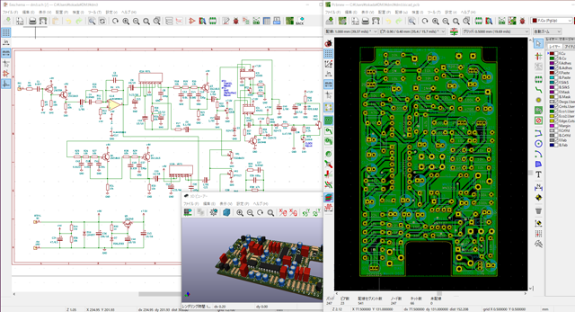
KiCAD screen shot
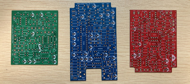
My own PCBs manufactured with Fusion PCBs
Surface-Mounted Chip Components in PCB Design
I recently embarked on an ambitious project to clone the high-gain distortion Suhr Riot using surface-mounted chip components. This involved mounting chip resistors, capacitors, and operational amplifiers on both sides of a compact 3.1 cm x 3.8 cm PCB that I designed. It's quite an enthusiast's endeavor, but the challenge and excitement were truly exhilarating!
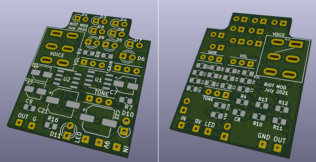
Purchase of parts
Through hall components (THD)
When purchasing electronic components, I highly recommend shops that specialize in effect pedal components. These shops allow you to buy resistors and capacitors individually, which is ideal for DIY projects. Additionally, they offer pre-painted aluminum die-cast enclosures, which are essential for effect pedal construction.
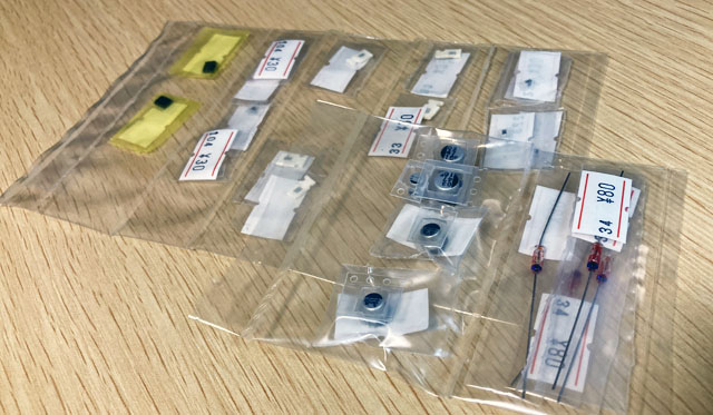
I personally prioritize painted enclosures, and recently, I sourced them from "Garrett Audio," a specialized shop for effect pedal parts here in Japan. Garrett Audio provides excellent service, meticulously packing ordered parts by their respective part numbers. Each bag is labeled with the resistance value handwritten, ensuring accuracy in component selection. I greatly appreciate their attention to detail and reliability.
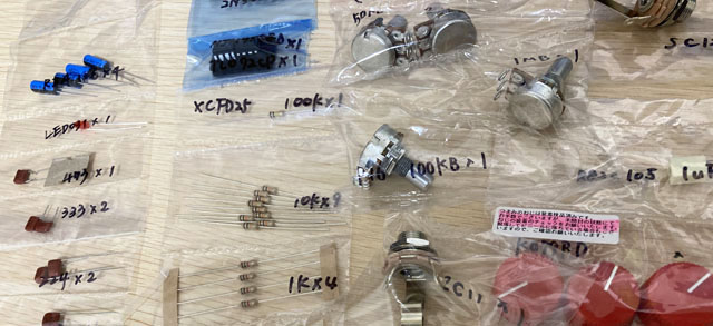
Surface mount components (SMD)
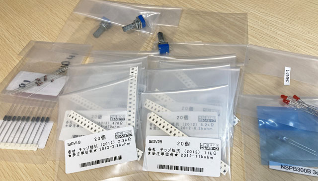
I've designed four PCBs using KiCAD, so I find it relatively easy to create PCBs even with surface mount components. However, I initially struggled with sourcing these components. Most Japanese online shops sell them in quantities of 20, 50, or 100 units, and not all shops stock all resistor or capacitor values. To navigate this, I searched for a supplier that offered smaller minimum order quantities and managed to procure resistors, capacitors, ICs, and other components needed for effect pedals.
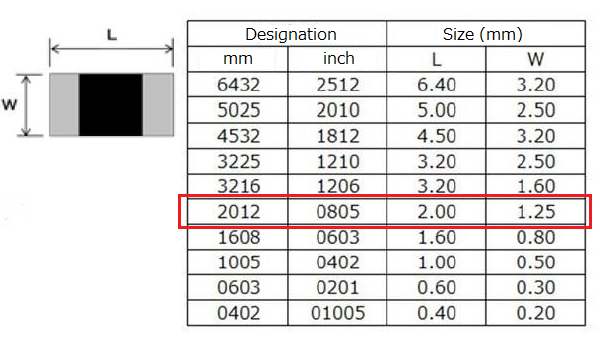
For resistor and capacitor values that weren't readily available, I had to combine multiple parts to achieve the desired constants. I opted for "2012" size (2.0 mm x 1.2 mm) for surface mount resistors and capacitors, as it strikes a good balance between size and ease of hand soldering. While there are smaller sizes like "1608" (1.6 mm x 0.8 mm), I found them challenging to solder manually.
For manual soldering of surface mount components, see the Riot clone article I first made with surface mount components.
Painted enclosure
Most effect pedal enclosures are typically made of die-cast aluminum. Among manufacturers, "HAMMOND" is quite popular. While silver unpainted enclosures can be found at regular parts stores, baked-painted enclosures are less common. Despite being a bit more expensive, painted enclosures have a stylish appeal.
The enclosure sizes I commonly use for effect pedals include:
HAMMOND 1590B: 60 x 112 x 31 mm (similar to MXR size)
HAMMOND 1590BS: 60 × 112 × 42 mm (MXR size with increased height)
HAMMOND 1590N1: 66 × 121 × 39 mm (slightly larger than MXR)
HAMMOND 1590A: 39 x 93 x 31 mm (recently popular mini size)
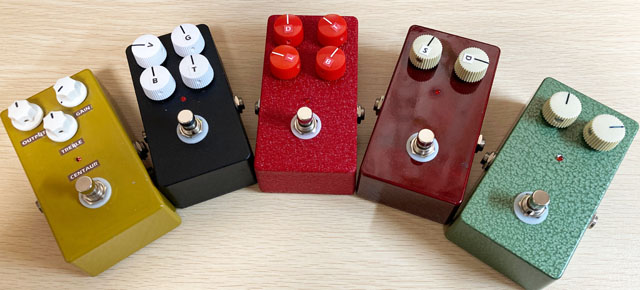
Black is 1590BS, all others are 1590N1
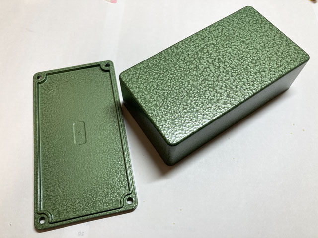
A new green painted enclosure
Required tools
Soldering Iron
Needless to say, the soldering iron is an indispensable tool. If you look at sites such as Amazon, it says "suitable for electronic work" or "suitable for board production", but the key points when choosing a soldering iron are the type of heater, wattage, and shape of the iron tip. Since the soldering iron will be used for a long time, it is recommended to choose a good one.
I am using a ceramic heater 30W soldering iron.
Type of heater
Nichrome heater
It is a soldering iron with a simple structure using nichrome wire and is inexpensive. It takes a relatively long time (2-3 minutes) for the temperature to rise sufficiently.
Ceramic heater
It has a structure that heats the iron tip with a ceramic heater, and tends to be more expensive than a nichrome heater. It takes a short time for the temperature to rise sufficiently, and empirically, it can be used within 1 minute. I think that the silver tip of the iron is short and suitable for detailed work.
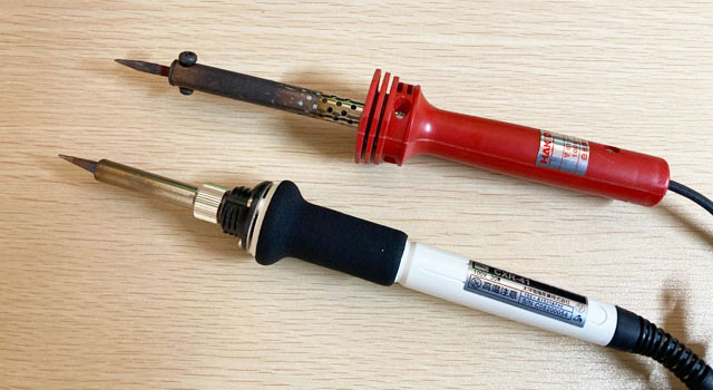
Red: Nichrome heater, White: Ceramic heater
Wattage
I recommend a wattage of 30W, preferably 40W. To make an effect pedal, you need to solder it to the phone jack in addition to the board parts. A 20W soldering iron for ICs is on sale for electronic work. However, the temperature does not rise and the solder does not melt when using 20W, especially for parts with large metal parts such as phone jacks.
On the other hand, if the wattage is higher, warming the part with a soldering iron for a long time may damage the part. If you get used to the soldering iron, you will be able to handle 40W, 60W and more.
Some soldering irons have a temperature control function, but they are expensive and are not necessary. There are also special battery-powered soldering irons, but I recommend not buying them.
Shape of soldering iron tip
We recommend that you use a sharp-edged soldering iron tip. Some have a flat tip, but they are not suitable for effect pedal production. Also, I think the shape of the iron tip should be straight and thin. For precision circuit boards, there is a soldering iron tip with an extremely fine tip, but it is difficult to handle because the temperature drops immediately when the solder is melted. Especially for parts with large metal such as phone jacks, the solder hardly melts.
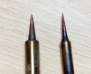
The left is recommended, the right is difficult to use because the temperature drops quickly
Solder iron stand
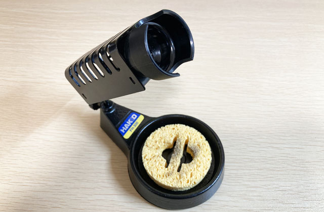
A soldering iron stand is also an essential tool. The soldering iron stand is equipped with sponge (soaked in water) that is convenient for removing dust such as tar on the tip of the soldering iron. Also, it is better to have a certain weight (about 500g or more) so that it will not fall when the iron is placed (inserted back). Making an effect pedal is a repetition of "soldering parts and returning the soldering iron to the soldering iron stand". I recommend choosing a stable soldering iron.
The iron stand differs depending on the type of heater mentioned above. The iron of the nichrome heater has a screw at the base of the tip, and it can only be inserted with a thick iron holder. There is no screw at the tip of the iron of the ceramic heater, and it is thin. The iron stand is "ceramic heater only", so be careful when buying a nichrome heater iron.
Solder wire, solder wick, solder sucker
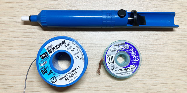
Solder wire is used much more than expected, so I recommend buying it on a reel. There are different types depending on the thickness and metal content, but the easiest to use is "1.0 mm thick, 60% tin / 40% lead, with tar" solder. If you buy 100g, you can use it for a while. You can buy it for about $ 10.
The solder wick is used to suck the solder to remove the parts if you accidentally attach the parts. You may not need it at first. But you can buy it for $ 3.
There is also a mechanical solder sucker (blue bar in the photo below), which may be for advanced users. This is a tool that pneumatically absorbs the solder melted with the tip of the iron. It's good for removing a lot of solder, but I don't think it's necessary at first.
Wire strippers, nippers, needle-nose pliers
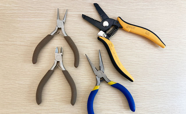
A "wire stripper" is a special tool for stripping wires. You can strip the wire with nippers, but I recommend buying it as normal nippers often fail because they cut the wire core. There are several types, so select the one that corresponds to the thickness of the wire to be used. I am using the one that corresponds to the wire of AWG24 thickness.
"Nippers" are mainly used to cut excess leads and wires of parts soldered to the board. I recommend a small one that is easy to handle.
Needle-nose pliers are mainly used to bend the leads of parts. Choose a small needle-nose pliers that is easy to handle with small electronic components.
Digital multimeter
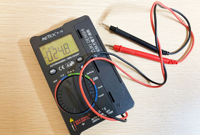
 A digital multimeter is also an essential tool. It is used only for checking continuity and measuring DC voltage, so there is no need for a multifunctional one. I still use the digital multimeter "P-10" that I bought in Akihabara more than 10 years ago for about $ 10. It looks cheap, but its small size makes it very convenient to use.
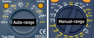
Nowadays, you can buy a digital multimeter with the necessary functions for about $ 20. The digital multimeter of the auto range (the dial has only symbols such as V, A, Ω) is convenient because it can be used just by selecting the mode. In addition, the specifications of the digital multimeter have a "count number" that indicates the maximum display value. It's hard to explain, but it's kind of precision. 4000 counts are the most common, but if you just want to make an effect pedal, you can use 2000 counts.
Electric drill, metal (ironwork) drill bit
It is used for drilling holes in aluminum enclosures. This is a must-have tool. A lathe drill is the best, but I don't think it can be placed in a normal home, so please purchase an electric drill that can be used as a screwdriver and for drilling holes. Most electric drills these days are rechargeable, but this charging is quite troublesome. If you only use it indoors, I recommend an AC-powered drill. It is ready to use, powerful and easy to handle. My first one was rechargeable, but it was troublesome to charge it before using it, so I replaced the second one with an AC power supply type.
For the drill bit (drill blade), select one for metal (for ironwork). Do not use woodworking drill bits as they are easily broken and dangerous. It is convenient to have a thickness of 1.5 mm, 3 mm, or 6 mm. The holes in the pods and jacks are large, such as 10mm and 13mm. Do not try to drill these large holes at once with a drill. Once you have drilled a hole to about 6 mm, it is sure to widen the hole according to the part with the taper reamer described later.
An important point when drilling holes in an enclosure is not to shift the center position. If you suddenly try to make a hole with a thick drill, the center position will shift. It is a good idea to first make a small hole such as 1.5 mm, then widen the hole with a 3 mm bit according to its center position, and then enlarge the hole with a 6 mm bit in the same way.
As a further note, when using a hand drill, use it as if you were shaving with a light force without pressing the bit of the drill. The 1.5mm bit will break easily if you push it with force. Even when opening with a thick bit such as 6 mm, do not press the drill body strongly. When using a 6mm bit, you should lightly shave a 3mm hole and expand it to 6mm. If you apply force, the enclosure will bite into the groove of the 6 mm drill and the enclosure will rotate together, which is extremely dangerous. Please work with work gloves. Be careful not to get injured.
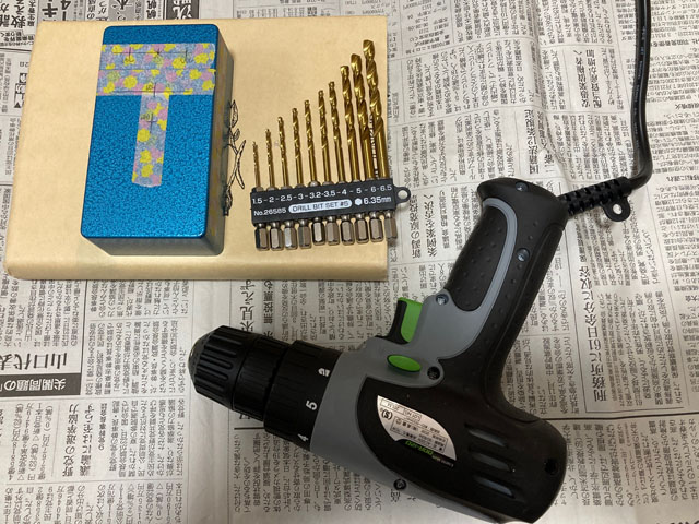
$25 AC power hand drill bought from Amazon
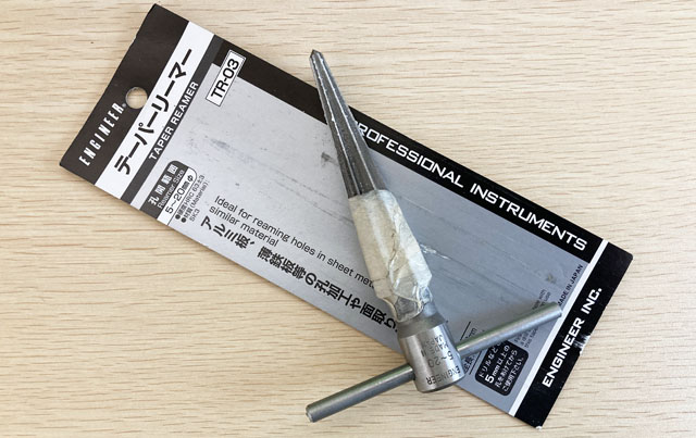
Taper reamer
The taper reamer is an essential item for drilling holes of various sizes. After making a hole of about 6 mm with a drill, use a taper reamer to widen the hole. Select a manual taper reamer. Insert it into the 6 mm hole drilled and turn it to widen the hole. After expanding it a little, try inserting the actual parts, and if it doesn't fit, expand it little by little. The hole size is different, such as 10 mm for the phone jack, 12 mm for the foot switch, and 13 mm for the AC adapter jack.
The aluminum enclosure is made of soft metal, so it's fairly easy to open holes. Expand it little by little so that the hole is not too large.
For how to use the taper reamer, refer to the effect pedal production article.
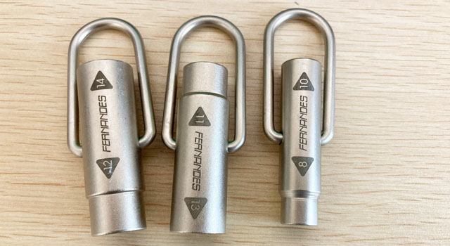
Socket wrench
This is mainly used to tighten nuts on switches and phone jacks. It's convenient, but you may not need it at first. Needle-nose pliers can be used as a substitute, but be aware that the tip of the pliers may scratch the surface of the enclosure.
I'm using "Fernandes SWR 1800".
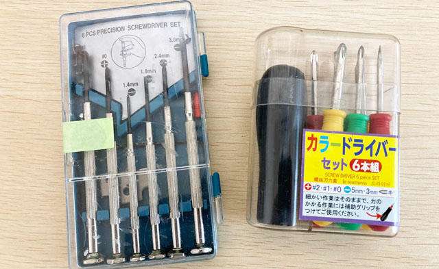
Screwdriver
A Phillips screwdriver is only used to close the back cover of the enclosure, so you can use whatever you have. However, you will need a small flat-blade screwdriver to tighten the pot knob.
Superglue
I use superglue to fix the ON / OFF indicator LED from the back side. "Jelly type" is suitable. I inserted the 3mm LED directly into the 3mm hole that I drilled, and fixed the LED and enclosure with superglue from the back.

Wiring wire (flexible type)
There are two types of wires used for wiring: the "solid type", which is made of a single wire with a thick core, and the "flexible type", which is made of a large number of twisted wires. The solid type retains its shape when bent, so the wiring is finished cleanly, but if the same part is bent several times, the core wire will break. For effect pedals, the board is often moved after wiring, so I recommend the "flexible type" that can be bent freely. The thickness is determined in units called "AWG". I recommend "AWG24" with a core wire of about 0.5 mm. I'm using a wire made in China that I bought from Amazon.
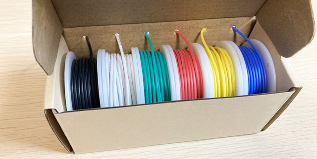
It is convenient to have a small cable tie. I use it to bundle the wires from the board to the pots and jacks for a clean finish.
The secret weapon "digital oscilloscope"
I bought a $45 digital oscilloscope from Amazon. Since it can be driven by + 9V, it is used with a 9V battery connected. (Note: Be sure that its DC jack is center positive inversely with effect pedals!.) You can use it for troubleshooting when there is no sound or for identifying the noise source. There is only 1 channel of input, and the measurable frequency is up to 200KHz. Although it has low specs for an oscilloscope, it has sufficient performance to measure audio equipment such as effect pedals.
Since it is an oscilloscope made in China, the same product is sold under many brands. If you want to buy one, I recommend the one with a probe (BNC probe for oscilloscope, not crocodile clip).
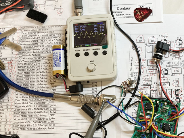
Finally, I got a full-fledged "Rigol digital oscilloscope"!
I liked the above small oscilloscope and used it, but I wanted a 2CH oscilloscope to see the phases of the two signals. Recently, I got a used "Rigol" digital oscilloscope on a used website. "Rigol" is a Chinese measuring instrument manufacturer, but recently it has become popular because it makes high-performance products at low prices. This oscilloscope has 100MHz / 2CH specifications. It is a model 10 years ago, but it has enough specifications for making effectors. With this, I think I can investigate the cause of any problem.
Actually, I had been working for an audio equipment manufacturer more than 30 years ago. At that time, I was developing using a cathode ray tube oscilloscope. I think it was made by Panasonic. Compared to the analog oscilloscopes of the time, this Rigol digital oscilloscope has the same basic functions, but it is super convenient to be able to memorize the measured waveforms. Depending on the amount of memory, I can see the waveform back from the trigger. And it's light, only 12 cm deep, dramatically smaller in size and easier to install.
Since it is usually used in a corporate laboratory, the fan noise is intensely noisy in a quiet home room, but I like it because it is much easier to use than the small oscilloscope I bought earlier. It seems that it also has an FFT function and a MATH function (which can calculate the waveforms of CH1 and CH2 and display them as waveforms), so I would like to try it.
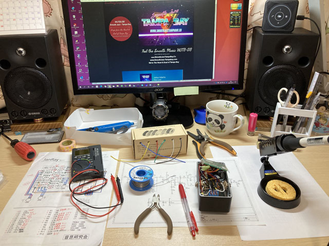
My work table
While making effect pedals, I am listening to my favorite internet broadcast "Tampa Bay Smooth Jazz". Be sure that it is safer to lay something on the table so that the solder does not hang down and burn the table.
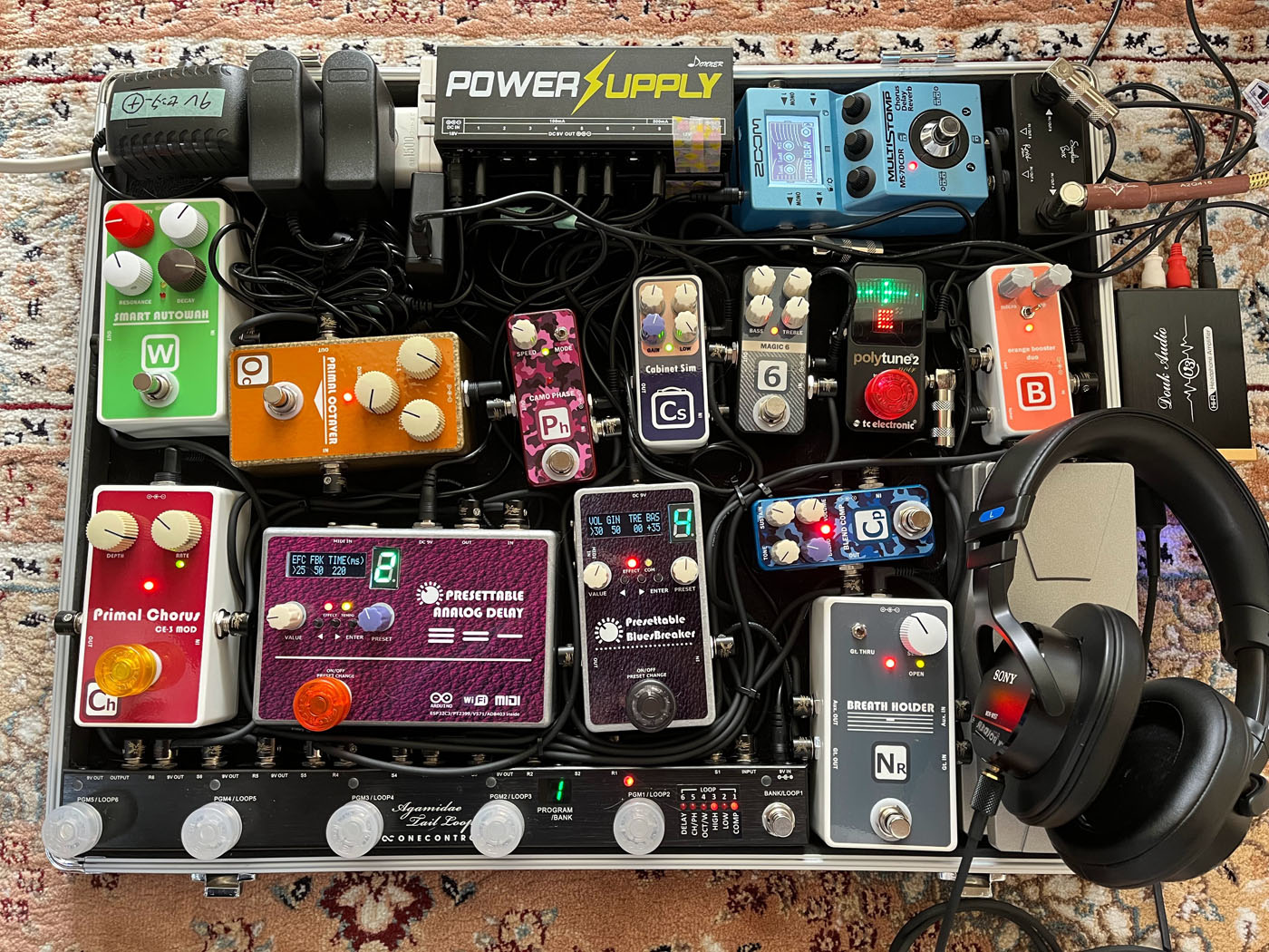
My latest pedal board
I replaced most of the pedals that I could make by myself. I replaced the phaser, octaver, compressor, and clean booster with my own work, and added a noise gate made in China that had better performance than my own work. For miniaturization, Jan Ray and BB-PREAMP were remade using surface mount components.
The final output of this pedalboard contains the self-made analog cabinet simulator so that the direct signal from this pedal board can be recorded through audio interface Steinburg UR22mkII.
The entire pedalboard weighs 10.4 kg (22.9 lbs).
Language
Self-made
effect pedals
- Pedals list page
 Tool selection
VEMURAM Jan Ray
Xotic BB preamp
Klon Centaur
 Revived old Chorus
 MXR Envelop Filter
 BBD Analg Delay DM-3
 600ms Analog Delay
 Arduino Analog Delay
 BBD Analg Chorus CE-3
CMOS Octaver OC-2
 Riot using chip parts
 Original design noise gate
 EP & MICRO AMP duo
 Keeley 4 Knob Comp
 MXR Phase 90 MOD
 Keeley Blend Comp
 DM-3 longer delay time
 ISP Decimator V2164


