[Latest!] Presettable Analog Delay using Arduino
Self-made Guitar Effect Pedals
Explore the articles to learn more about your favorite effect pedals.
|
Control analog delay knobs with a microcomputer
So far, I have made many guitar effect pedals that stick to analog. Analog pedals change the sound by turning a variable resistance (volume) knob. The low-noise analog delay that I made last time, which is a combination of PT2399 and noise reduction chip V571, also has three knobs (delay time, level, and feedback).
This time, I made my own analog delay that controls the variable resistors of these three knobs with a microcomputer and allows to preset the settings of the knobs.
Preset value editing via WiFi and preset selection via MIDI
Feasibility check
 So far I've used breadboards to check the feasibility of WiFi and MIDI controllers working with Audiono. Using the libraries supplied with Audiino, I found it very easy to send and receive MIDI, send and receive HTTP data using WiFi.
Goal of this self-made
Based on the items that I confirmed the feasibility, I made my own analog delay pedal with the following functions.
Edit pedal knob settings using a browser of PC or iPhone
Functions to preset settings for the pedal's knobs (delay time, level, feedback) using a PC or iPhone browser by implementing an HTTP server in the pedal
Preset switching via MIDI
The function to switch presets during performance by MIDI signals (program change) from the switcher by implementing MIDI
Selection of controller device
In order to realize an analog delay that allows preset value editing via WiFi and preset selection via MIDI, I selected the following devices.
Microcomputer board "XIAO ESP32C3"
 For the microcomputer that controls the pedals, I searched for something as compact, multi-functional, and inexpensive as possible.
I was looking for an Arduino-enabled board that could be easily programmed in C/C++. Then, I found a board (module) for IoT called "XIAO ESP32C3" released by Seeed Studio in China, which is small and equipped with WiFi. The price of less than $10 was also attractive, and it was perfect for this purpose.
Digital pot "AD8304"
In order to control the three pots (variable resistors) of the analog delay, I used a "digital potentiometer" that can change the resistance value with a microcomputer.
There aren't many types available online, but I chose "AD8304" from Analog Devices, which I found at Kyoritsu Eleshop in Japan.
It has four built-in variable pots of 100kΩ and can be controlled with a 3-wire serial signal. However, since the power supply voltage is 5V, the voltage range available for the variable pot is 0 to 5V. Therefore, when using a 9V analog effect pedal, it was necessary to pay attention to the voltage range of the signal.
LCD character display
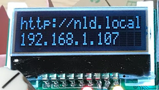 I used a 16-character x 2-line LCD character display (AQM1602Y) to display parameters such as effect levels. It is cheaply sold at Akizuki Denshi Tsusho.
It can be used simply by connecting to the "SDA" and "SCL" terminals of the ESP32C3 with I2C. The 3.3V power supply output by ESP32C3 is used as the power supply. Built-in characters can be easily displayed using the Arduino display library "ST7032" which is a LCD controller device.
Rotary encoder
A rotary encoder (Alps Electric's "EC12E series") was used to set the knob values. I used the non-click type. It detects the direction of rotation with a 2-wire pulse signal. I implemented it with reference to encoder rotation detection software found on the Internet.
To fix the board to the enclosure, I choose the type that can be fixed with a nut.
Connection between microcomputer and peripherals
Implementation method with a small number of ports
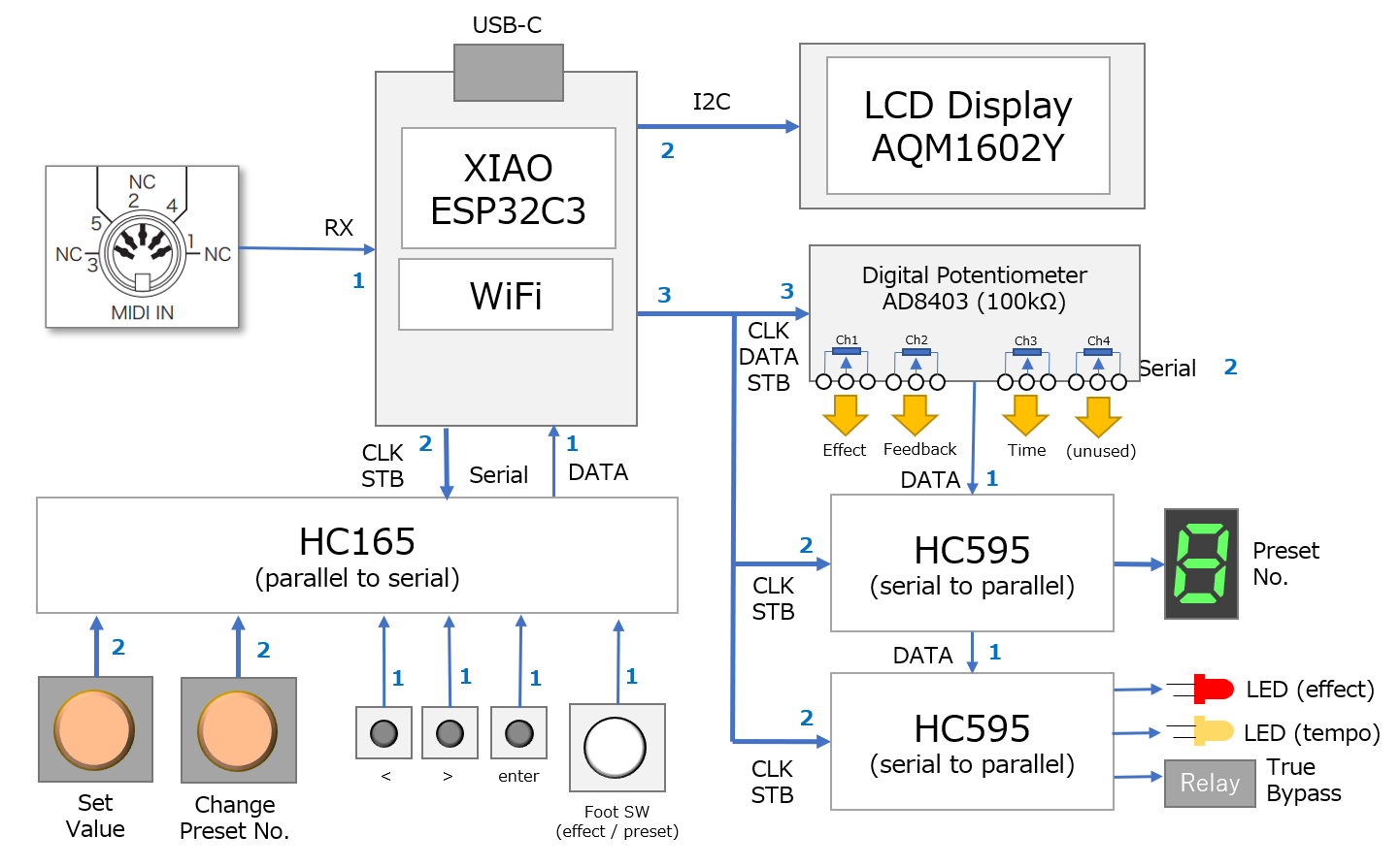
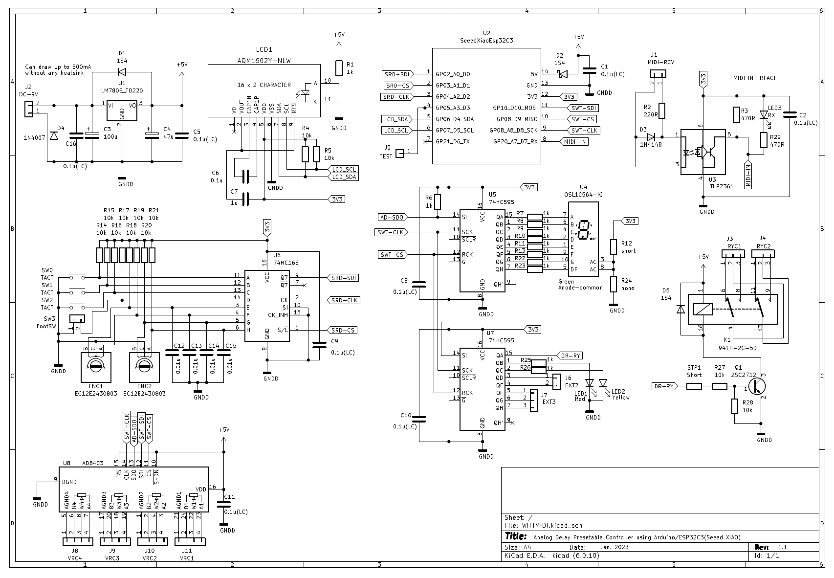
Since the "XIAO ESP32C3" is ultra-compact, it has only 11 I/O ports. Therefore, in order to increase the number of devices that can be connected, all connections with peripheral chips are serial connections. Nine general purpose ports are used.
LCD Display: Connect using I2C on ESP32C3
Button, rotary encoder input: Connect via HC165 (parallel to serial converter)
LEDs, Relays, Digital Pots: Connect a digital pot and two HC595s (serial to parallel converter) in series
System configuration
Below is a diagram of the system configuration.
Pedal control software
Software structure
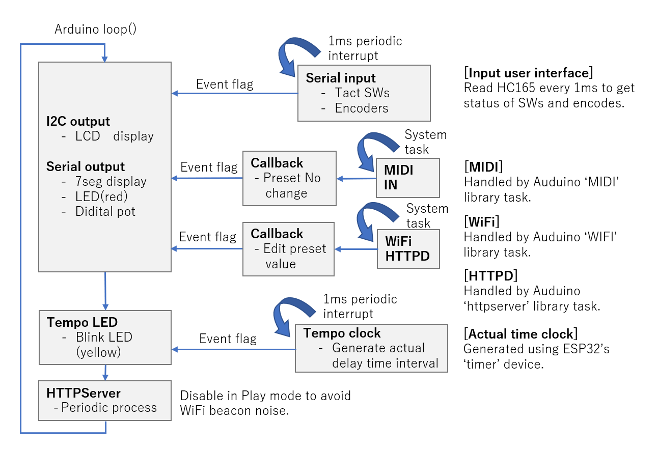
The control of this pedal was programmed in C/C++ using an Arduino. Arduino does not have a multitasking OS, and the main part runs in a polling loop with the function name loop(). The ESP32C3 used has four timer counter functions, and periodic interrupt processing can be easily achieved by simply specifying the interrupt handler function using the Arduino API.
Therefore, I used periodic interrupts (1msec intervals) to capture button and rotary encoder operations. The polling loop is notified with an event flag when a button or encoder changes. Due to the relatively slow interrupt interval, malfunctions due to chattering of buttons and encoders are rare.
The main processing methods are:
Main loop (Arduino loop function): It is an event loop, and includes processing for LCD display, 7 segments connected to HC595, LED, and serial control of digital pots.
Input from button, rotary encoder: Triggered by 1ms period interrupt. When a button press, long press, or rotary encoder left/right rotation occurs, the event type is put into a variable and an event flag is set. The flag is always seen in the event loop mentioned above, and when the flag is raised, the corresponding input is processed.
MIDI: This is implemented using standard library functionality. When a signal comes to MIDI-IN, the callback function is called, so the callback simply processes the MIDI channel and input value.
WiFi: This is also achieved using libraries. Since it uses WebServer, the mechanism is a little complicated. This method is explained in the article when I tried WiFi for the first time.
Tempo LED: A yellow LED blinks according to the delay time. As with button input, this creates a 1ms clock counter with a 1ms periodic interrupt callback function and measures the time. The actual time is calculated according to the delay time setting, and the blinking flag is sent to the event loop at that time interval.
A software configuration diagram is shown below.
Implement WebServer and edit presets in browser
It uses Arduino's WiFi and WebServer libraries to implement the ability to edit presets in a browser on a PC or iPhone. Bluetooth can also be implemented, but it is difficult because it is necessary to create a dedicated application for PCs and iPhones. On the other hand, in the case of WebServer (HTTPD), it is much easier to create applications for PCs and iPhones because they can be run in a browser just by writing HTML.
The created HTML is a simple one that accesses "http://nld.local/" to display the preset values inside the pedal, and manually changes 10 preset values to rewrite the presets. Editing is still easier than using a pedal knob.
By making full use of HTML and JavaScript, I think it is possible to create even more advanced editing functions.
WiF/WebSerer implementation details can be found on this page.
Fine software control
With an analog delay, if you turn the delay time knob while the sound is still playing, the pitch of the delay sound changes. This is because the delay time of the analog delay varies depending on the operating frequency (equivalent to the sampling frequency), not the length of the delay line.
The same thing happens with this pedal when switching presets and changing the delay time. To prevent this in my program, I set the effect volume to 0 to mute the delay sound at the moment the preset changes, and set the feedback volume to 0 so that no sound enters the delay line. After the delay time (up to 580ms), I set the effect volume and feedback volume of the switched preset.
By controlling in this way, even if you switch presets, you can prevent abnormal sounds with different pitches.
Details on how the digital pot "AD8304" works can be found on this page.
Method of operation
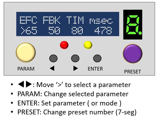
It is operated with two rotary encoders (VALUE, PRESET), three tact switches, and a foot switch. The set value is displayed on the character LCD of 16 characters x 2 lines.
The basic operation method is to select a parameter with the "< >" button and change the parameter value with the "VALUE" rotary encoder. Then press the "ENTER" button to confirm the changed parameter and mode.
The "ENTER" button can be short-pressed or long-pressed, and a long-press will display the setting menu screen. There, you can change the settings in the pedal, such as MIDI receiving channel, WiFi enable/disable, foot switch mode (effect ON/OFF or preset switching).
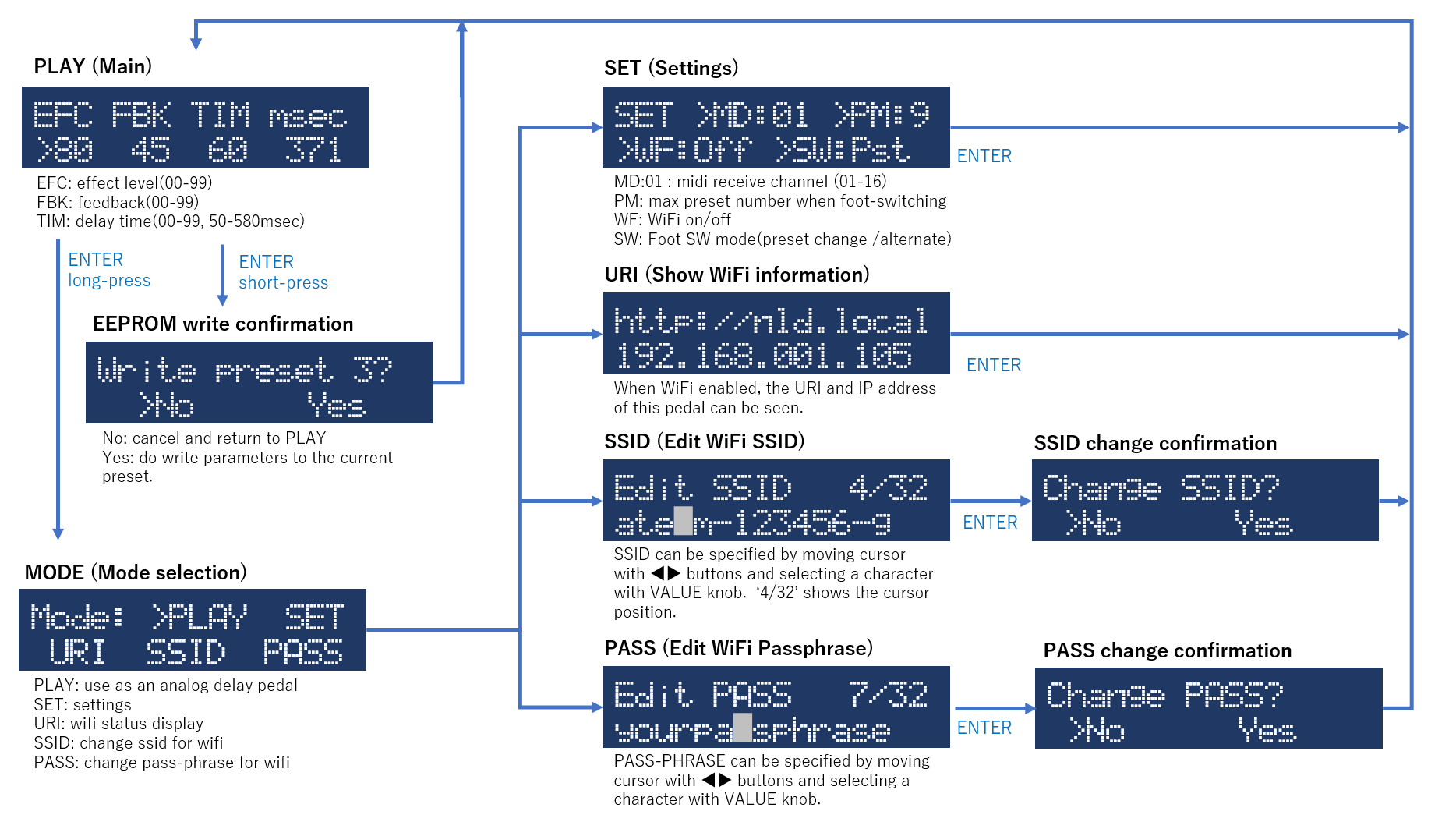
UI specifications
Pedal operating specifications are shown below. "PLAY" mode is used when playing. Selecting a preset sets the EFFECT, FEEDBACK, and TIME parameters. When you change the setting value with the "< >" button and "VALUE" knob, a decimal point is added to the preset number of the 7-segment LED, indicating that the preset has been changed. Pressing ENTER will ask if you want to overwrite the current preset.
WiFi SSID and PASSPHRASE can also be edited with the "< >" button and "VALUE" knob.
See the YouTube video below for details.
Source code
You can view it on Github. It is complicated because it is packed with functions, but I think it can be partially used.
Breadboard and schematic
After making a prototype on a breadboard and confirming the operation, I wrote a circuit diagram.
Analog delay board
Modified the previous self-made noiseless analog delay
I modified the printed circuit board of an analog delay pedal that combines the PT2399 and noise reduction chip V571 that I made last time. The three pot parts have been replaced with connectors so that they can be connected to the digital pot described later.
The three 3P connectors on the top are for connecting to the True-Bypass relay and the IN/OUT phone jack. Although it is not mounted yet in the photo, the power supply (9V, GND) is also connected with a 2P connector.
Analog delay pots voltage range adjustment
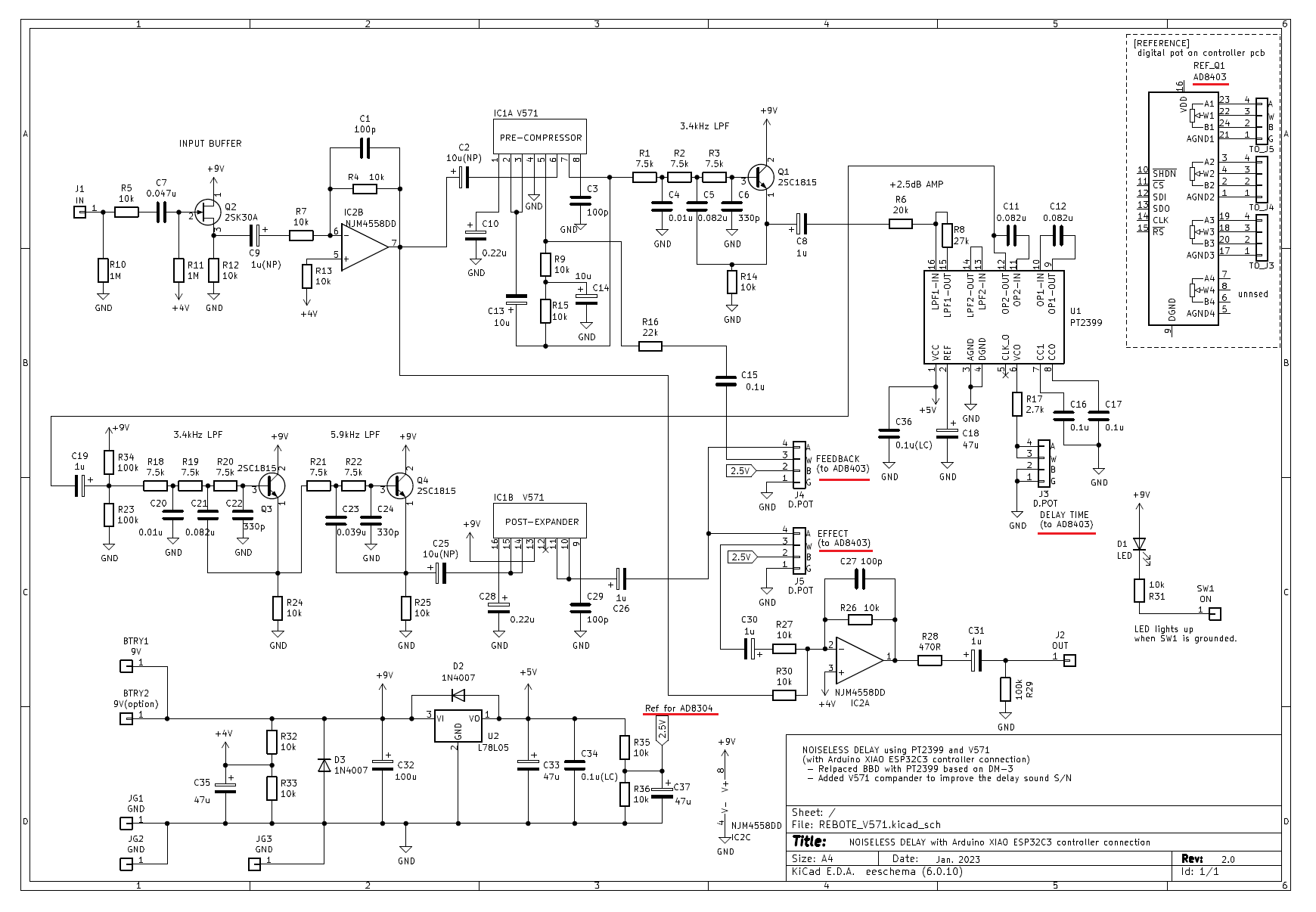
The three variable resistors included in the analog delay circuit can be replaced with the variable resistors of the digital pot "AD8304". The working voltage of the digital pot is up to 5V. Therefore, the effect level and feedback level offset voltages must be adjusted to match the voltage of the digital pots.
I made it with two resistors and an electrolytic capacitor to shift the reference voltage to 2.5v.
The delay time is determined by the resistance value connected to the PT2399 pin. The working voltage of the PT2399 is 5V, which is the same as the digital pot, so I connected it directly to the digital pot.
Circuit diagram
The circuit diagram with the connector for connecting to the digital pot "AD8304" is shown below. The connection with the controller board is indicated by a red line.
Design the controller PCB
Designed with KiCAD and manufactured with PCBgogo
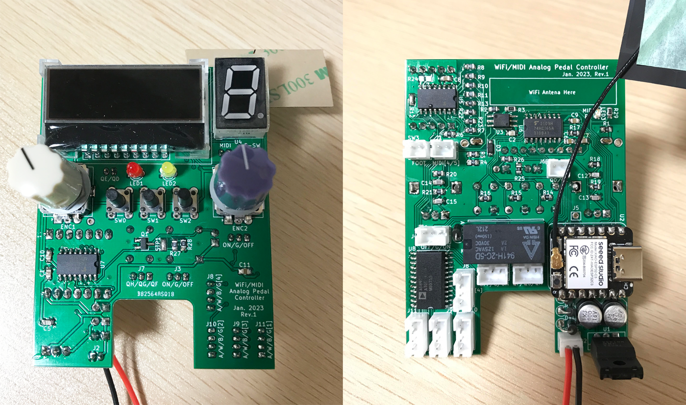
I designed a printed circuit board based on the circuit diagram above. As usual, I designed it with KiCAD and had it made by PCBgogo in China. This time, I made it 6 cm * 8 cm so that it can fit in TAKACHI's die-cast enclosure "TD-10-15-4N" (10 cm * 15 cm * 4 cm) together with the analog delay board mentioned above. The bottom of the board is cut out to make room for the footswitch.
The microcomputer board has a WiFi function, and a WiFi antenna is connected with a very small connector. In order to emit radio waves from the LCD hole of the aluminum enclosure, I stuck an antenna under the LCD. For that reason the ground pattern (solid ground) under the LCD was removed.
The LCD and microcomputer board parts are not included in the KiCAD library, so I made them myself. Most of the other parts were available from the standard library. Due to the small board area, the components and connectors are tightly packed.
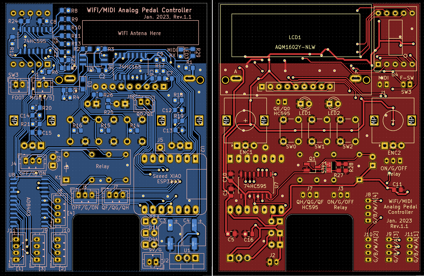
PCB made by PCBgogo
(Thanks to PCBgogo for making it right every time, even though it's only a $5 prototype!)
KiCad PCB design data
The PCB data created using "KiCad (Windows 64-bit) Version: (6.0.4), release build" is provided. The ZIP file contains the schematic, board design data, and original component data. Please read the terms of use and disclaimer in the attached "readme.pdf" before using this data.
Mounting components on PCB
Mounted using surface-mounted components
The controller board was designed with surface-mounted components, so there are a lot of components on the front and back of the PCB.
Use pin sockets for connections between boards
For the first time, I used 2mm pitch pin sockets for connection. I also bought a special tool for crimping pins and wires. Because the pin is so small, crimping the wire takes a lot of practice. I failed repeatedly before I could get used to it, and wasted about 10 pins. Now that I've gotten used to it, the crimping work is comfortable and smooth.
Operation check
One-shot operation without major trouble
I've confirmed the operation on the breadboard, so I thought it would work without any problems. However, there was a problem that characters were not displayed on the LCD at first. When I reviewed the circuit diagram, I found that the I2C CLK and DATA were wired in reverse, and the board was made as it was. I have no choice but to cut the pattern and reconnect it with wires.
I checked the same circuit on a breadboard, so I didn't have any troubles other than the above, and didn't need to use my oscilloscope.
Put it in the pedal board and check the operation and volume level with my kitty
Beacon noise due to WiFi power consumption
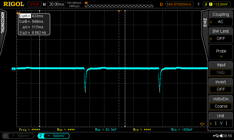
I have implemented WiFi using Arduino. When WiFi is turned on, radio waves called "beacons" are emitted to communicate with the router every 100msec. A large pulse noise occurred on the 9V power line, probably because the power consumption for sending radio waves was large. As a result, the effect sound produced a rather loud "popping" sound.
I tried putting in a capacitor, but it didn't work at all, so I gave up on using WiFi and effects at the same time. The software has been changed to turn off the WiFi function when playing the guitar (in PLAY mode).
Overall current consumption (measured at 9V DC terminals) is:
WiFi OFF (during normal play): 95mA
WiFi ON (when connected to router): 105mA
Process aluminum die-cast enclosure square holes
Square hole processing is difficult
The hardest part of this self-made work was the processing of making a square hole in the die-cast enclosure. Round holes can be easily drilled with a hand drill and reamer. However, square holes can only be cut with a file, and die-cast enclosures are more than 2 mm thick aluminum, so it was not easy.
Actually, I was impressed by watching a YouTube video of an automatic processing machine from a certain manufacturer, and asked them to estimate the processing of the enclosure. However, since the estimated amount was over $180, I got a little discouraged and decided to do it myself.
I feel sorry for the blueprint creator of a certain manufacturer and the agent who responded politely.
How to determine the hole position
This time, I had made a processing drawing when I requested an estimate, so I pasted the drawing on the enclosure and decided the hole positions. My home inkjet printer has poor length precision, so through trial and error, I confirmed that if I print at 94.5%, I can print almost the actual size.
I pasted this on the enclosure, punched the center of the hole and the corner of each hole, and processed it based on this.
Confirm that 44mm on the drawing is actually printed at 44mm
square hole drilling
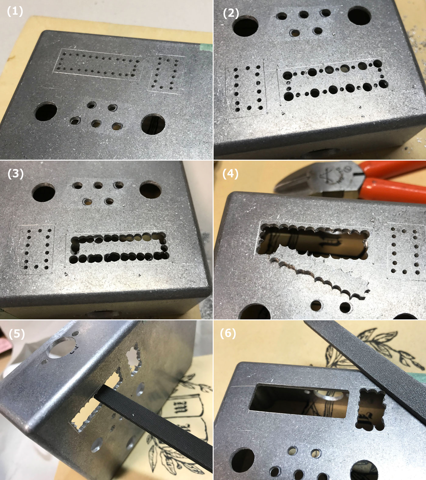
The method of drilling a square hole is as follows. The entire process took about 3 hours.
(1) Draw a square hole line on the case based on the corner punch of the square hole. (I scratched it with the tip of a sharp screwdriver.) Inside each hole, punch at 3mm intervals so as to connect the holes with a 3mm drill, and make a 1mm hole as a reference hole. At this time, make it about 2mm inside so that it does not go beyond the line when drilling a hole with a 3mm drill.
(2) Make a hole with a 3mm drill every other one. The reason for drilling alternately is that if you try to drill a hole right next to it with a hand drill, the drill will bite into the hole that you drilled first, and the case will be pulled as the drill rotates, which is dangerous.
(3) Drill holes so as to connect every other hole. If the holes you drilled earlier are close together, it is better to use a drill with a smaller diameter. As mentioned above, be careful not to bit into the pre-drilled hole.
(4) Cut off the gaps between the holes that are not connected with a nipper to make a larger hole.
(5) Use a metal file (rough, small size is best. HOZAN K-172 is best) and scrape down to the line of each hole. This is hard work that causes muscle pain. Scrape a little at a time, being careful not to cross the line. Be careful not to injure yourself with the burrs opened by the drill. I think you should wear gloves.
(6) The square hole for the LCD display is completed.
Square hole processing result
It wasn't as accurate as a certain manufacturer's processing machine, but I'm satisfied with the result. It was especially difficult to sharpen the corners. When I cut the corner, I went over the line. As a result of repeating this, the hole gradually became larger.
Also, regarding the 7-segment hole, the dimension given from the board design drawing was off by about 0.5mm, so it didn't fit perfectly and ended up with a slightly larger hole.
However, I am satisfied with my work.
Completion of installation in enclosure
Connect wires with pin socket
The connection between the boards was very smart because I used a pin socket this time. The pin sockets and wires are sturdy and I think they are very reliable.
To fix the analog delay board, I used a spacer like the one in the photo below to mount the board at a height of 18mm or more so that the phone jack would fit under the board. I fixed the enclosure with double-sided tape and screwed the board.
Create case label
I created a label using a special sheet that can be created with an inkjet printer. I named it "Presettable Analog Delay" and added the Arduino, WiFi and MIDI logos. I tucked the label inside each hole so that the aluminum edge is not visible.
Completed "Presettable analog delay"
(Addition) Connect with BBD version analog delay board
In addition to the analog delay board using the PT2399, I tried connecting the BBD version analog delay (surface mount) board. I used pin sockets this time, so I removed the pots on the BBD analog delay board, added pin sockets, and connected them to the digital pots on the controller board.
The analog delay in the DM-3 circuit is 50kΩ for all three pots. It matched the resistance value of the digital pot used this time, and there was no need to adjust the circuit constant. Also, the pot of the LFO circuit that determines the delay time was applied with a voltage of 2.2V to 4.7V, which is within the operating voltage range of the digital pot. Therefore, I just replaced all pots with digital pots.
The Arduino software has been modified to match the BBD version of the pot. I added "#ifdef PT2399" to the GitHub source code so that I can switch between the PT2399 and BBD boards.
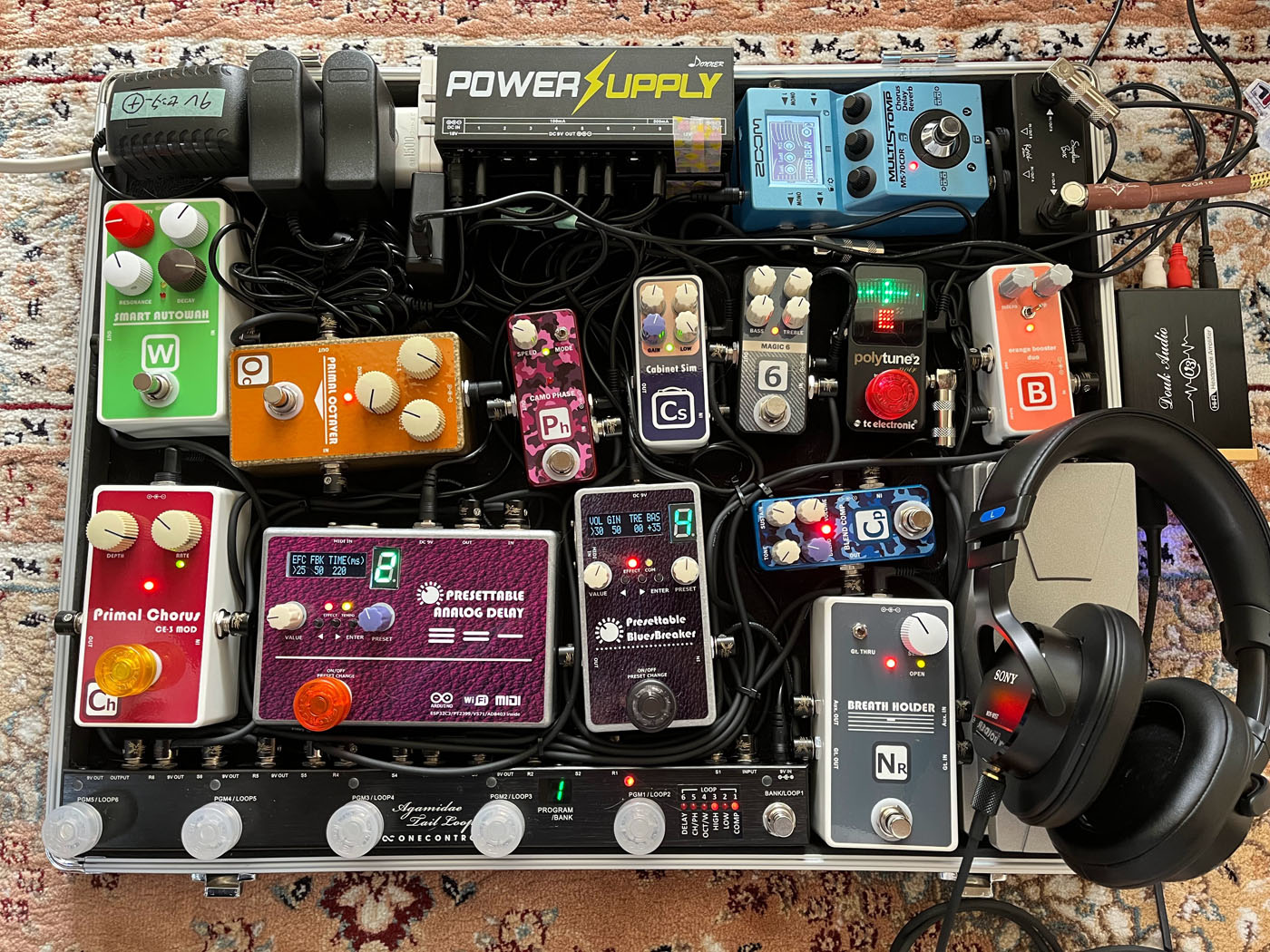
My latest pedalboard
I removed the digital delay and replaced it with a presettable analog delay. Except for the reverb and tuner, all effects have been self-made.
Lastly (prototype and Chinese technology)
Amazing preset feature
By pressing the footswitch (momentary type) of this pedal, you can switch presets and instantly change the delay time and feedback. Since you can change the effect according to the song you are playing, it has a wide range of uses and is extremely effective.
You can edit the preset values inside the pedal from your iPhone's browser using WiFi, so you don't have to get on your knees and fiddle with pedal knobs to change preset values.
Presets can be changed via MIDI, so if you have a MIDI controllable switcher, you can program analog delay effect patterns into the switcher's presets.
There are many multi-effectors and digital delays on the market that can be used in this way, but I think analog delays are rare. (It's a pretty maniac delay, but you can find Suhr Discovery Delay.)
Arduino is insanely easy
Arduino is super easy to build small embedded software. If you want to blink an LED, you can do it in 15 minutes. No basic technology such as Linux or real-time OS is required to incorporate it into a microcomputer. With just a polling loop and an interrupt, you can easily do anything, such as WiFi, Bluetooth, USB serial communication, etc.
After all, I think it's great that you can buy an Arduino board anywhere cheaply and get started right away.
A Chinese manufacturer that is open to self-made/prototypes by students and individuals
Printed circuit board manufacturers FusionPCB and PCBgogo in China are open to prototyping, offering 10 printed circuit boards for $5. It can be used by both individuals and students.
Without the service of this Chinese board maker, I would not have been able to design boards with KiCAD, and would not have enjoyed making many effect pedals myself. I am very grateful to FusionPCB and PCBgogo in China.
China's IoT hardware development technology may be the best in the world
The Arduino-programmable IoT board “XAIO ESP32C3” equipped with WiFi that I used this time is also released by a Chinese company called “Seeed Studio” (the same company as the board manufacturer FusionPCB). "Seeed Studio" sells devices that can be used for self-made/prototyping, and I think that China is the world's number one not only for manufacturing but also for hardware development technology.
This time, I had a hard time drilling a square hole in the enclosure, but I learned a lot.
Language
Self-made
effect pedals
- Pedals list page
 Tool selection
VEMURAM Jan Ray
Xotic BB preamp
Klon Centaur
 Revived old Chorus
 MXR Envelop Filter
 BBD Analg Delay DM-3
 600ms Analog Delay
 Arduino Analog Delay
 BBD Analg Chorus CE-3
CMOS Octaver OC-2
 Riot using chip parts
 Original design noise gate
 EP & MICRO AMP duo
 Keeley 4 Knob Comp
 MXR Phase 90 MOD
 Keeley Blend Comp
 DM-3 longer delay time
 ISP Decimator V2164


