Self-made analog chorus pedal using BBD (BOSS CE-3 MOD)
Self-made Guitar Effect Pedals
Explore the articles to learn more about your favorite effect pedals.
|
Full analog chorus using BBD
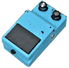 Among the guitar effect pedals, the "chorus" is popular. Compared to modern digitized chorus pedals, traditional analog pedals are more popular because they can produce thicker and deeper sound.
Actually, a while ago, I disassembled the YAMAHA chorus CH-01 (which I bought 30 years ago) whose switch was broken, made it a True-Bypass specification, and put it in a new enclosure. Probably because that its BBD has only 256-stage buckets, it made a lighter sound than the BOSS chorus.
So, I tried to make a BOSS CE-3 MOD, king of chorus pedal using a low price 1024-stage bucket BBD.
BOSS CE-3 Analog Chorus BBD Chip
 The schematic of the BOSS CE-3 analog chorus can be found in the service manual for repairs. However, the CE-3 uses a 1024-stage BBD chip "MN3207" made by Matsushita. This chip is no longer manufactured and may be expensive or a suspicious used chip extracted from some gear.
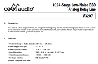
A semiconductor company Coolaudio has a second source product "V3207" compatible with "MN3207". You can buy this chip for just $1. The clock generator V3102 used together costs only 80 cents. So I decided to make a chorus pedal using Coolaudio's second source ICs.
By the way, the previous generation BBD "MN3007" is used in the famous BOSS chorus CE-2 released in 1979. This chip is no longer available. On the other hand, it seems that the same "V3207" is used for the latest chorus pedal CE-2W that was revived in the "WAZA" series in 2016.
Self-made based on the circuit of BOSS CE-3
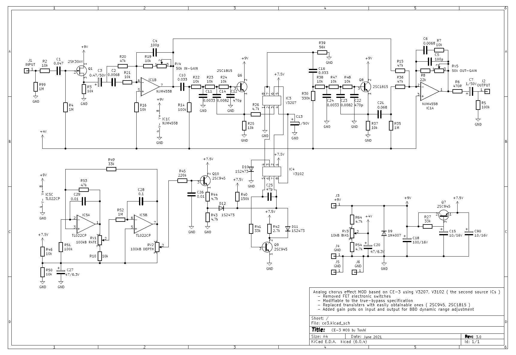
The schematic can be found in the BOSS CE-3 service manual. The BOSS effect pedals have an ON / OFF foot switch that is not a mechanical switch but FET electronic switches. In order to make it the True-Bypass specification, I removed all the FET switches from the schematic. The CE-3 has a stereo output, but I removed it as well.
Order the original 2-layer PCB from "Fusion PCB"
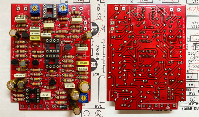
This time as well, I designed the printed circuit board myself like the previous analog delay self-made (DM-3 MOD), and ordered it from "Fusion PCB" in Shenzhen, China, who produces 10 PCBs for $ 5. The board design was done using the freeware "KiCAD" for all processes.
The manufacturing fee is only $ 5, but the shipping fee by DHL is $ 20, so the total is $ 25. Still cheap enough.
When ordering with FusionPCB, you can select the resist color (green, red, blue, etc.), but this color selection seems to affect the delivery date. I think it depends on the manufacturing situation of the factory at that time, but the most common color "green" is delivered fastest. I chose "red" this time, but the scheduled delivery time was longer, and it took 12 business days from ordering to completion of production. DHL delivery took other 5 business days.
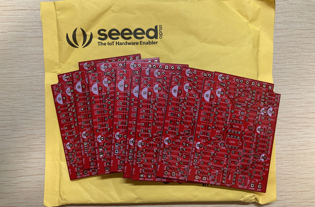
My own original PCBs
PCB design with KiCAD
All processes of PCB design can be done with the freeware "KiCAD". I used KiCAD Ver.5.19. It can be created only with the parts library provided by default. The trace design is fairly easy since the two-layer board can draw trace on the front and back. I connect all the lines except GND, and filled all the remaining GND with solid earth.
The board size was decided to be 60mm wide according to the enclosure "HAMMOND 1590N1" width inside. I shortened the length of PCB while placing the parts, and finally it was 80 mm.
Board design requires some experience (I worked for an electronics design company about 25 years ago). There are many books on CAD and board design methods, so you can refer to them and make your own.
PCB design free software "KiCAD"
KiCad PCB design data
The PCB data created using "KiCad (Windows 64-bit) Version: (6.0.4), release build" is provided. The ZIP file contains the schematic, board design data, and original component data. Please read the terms of use and disclaimer in the attached "readme.pdf" before using this data.
Obtaining parts
I bought all the parts this time at Garret Audio (a parts shop in Tokyo). Coodaudio's BBD chipset "V3207, V3102" can also be purchased in Akihabara.
As for the transistor for small signal, 2SC945 and 2SC732 are used for the original CE-3. The 2SC732 was difficult to obtain, so I used the alternative "2SC1815".
In addition, "2SK30A-Y" is used for FET. This is also not manufactured and difficult to obtain, but I was lucky enough to buy it. If you can't get it, "2SK2880" can be used instead.
Others are ordinary electronic components. The resistors are 1/4W 5% carbon, the capacitors is cheap box type or ceramic type, and the electrolytic capacitors are also the cheapest.
Coolaudio's second source ICs
Parts mounting and soldering
I put the purchased parts on the PCB. For me as a self-made nerd, soldering parts is the most enjoyable task. This fun work was completed in about two hours.
Operation check and adjustment
Adjustments
For this self-made work, I added an adjustment pot (semi-fixed) that the original CE-3 does not have. They are the gain adjustment of the input op amp and the output op amp. The input gain was added for the purpose of determining the input level to the BBD. I thought it would be better to drive the BBD at the highest possible level in order to improve the SN.
The output gain is intended to eliminate the audible level difference when the True-Bypass switch is turned on / off.
In addition, there is a pot that adjusts the bias voltage of the BBD peripheral circuit. This is a BBD distortion adjustment. This adjustment requires a sine wave generator and an oscilloscope. Input a 200Hz sine wave from the input jack and monitor the 1st pin (emitter) of Q8. Gradually raise the input level and turn the BIAS pot where either the top or bottom of the sine wave clips, adjusting to the point where the distortion of the sine wave is minimal (where the sine wave is shaped to be clean).
Since I don't have a signal generator, I used the free software "WaveGene" to generate a signal and input the signal from the audio interface "UR22mkII" to this chorus pedal. I'm using a small digital oscilloscope I recently bought from Amazon for $ 40 to see the waveform.

Adjusting BIAS to minimize distortion
The sound came out in one shot without difficulty. I will decide the input and output gains while using it actually later.
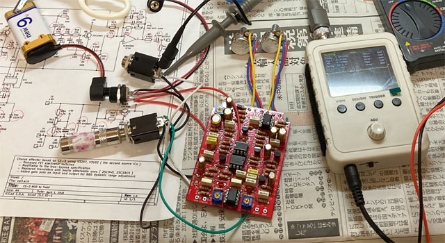
Checking the operation on the desk
Built in the enclosure
Enclosure processing
I housed this ovtaver in a white-painted enclosure of HAMONND's "1590N1". I call it "White Chorus".
The enclosure was processed using a hand drill. After positioning, the holes were expanded in the order of 1.5mm, 3mm, and 6mm, and then expanded to the hole diameter of each part using a taper reamer.
Chorus BOSS CE-3 MOD drilling process
Placement image in the enclosure
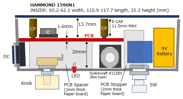
I designed the component placement so that the phone jack and foot switch do not interfere with the PCB. In addition, the position of the switch was decided so that the battery space could be taken. The small Switchcraft box-type phone jack (# 112BX) can be used.
I made a 3mm hole and pushed the LED from the inside and fixed it with super glue. I don't use the uncool LED holder. If you want to make it in the same way, please refer to the figure below.
Build into enclosure
To make it look good, I put the board with the parts facing outwards. Therefore, in order to avoid interference between parts such as phone jacks and the PCB solder surface, a thick paper spacer with a thickness of 2 mm and a height of 20 mm is attached to the inner side of the enclosure with double-sided tape to support the board.
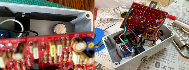
A spacer of the board is attached to the inside of the enclosure to keep the height of 20 mm.
(The parts on the back of the board are decaps for noise suppression.)
Beautiful white chorus inside
Sound sample
The same phrase will be played twice. The first one is OFF (clean) and the latter one is this CE-3 MOD.
Recording environment: Fender Stratocaster
-> Self-made chorus
-> ZOOM G3X (Fender Twin Reverb clean simulation)
-> UR22mkII
-> DAW (Studio One)
![]() Sample: Chorus effect comparison (MP3)
Sample: Chorus effect comparison (MP3)
I've created a page about the tools you need to make your own effects pedals and the basics of how to make them. See here for details..
My latest pedal board can be seen on this page.
[Additional MOD] Added RATE (chorus cycle) indicator
I added an LED indicator that shows the chorus cycle. The chorus creates a double-sounding effect by periodically changing the pitch by changing the period of the clock sent to the BBD with the triangular wave generated by the LFO. So, I tried blinking the cycle with an LED.
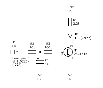
The method is extremely simple. Just use the square wave generated by the multivibrator of the LFO circuit as it is. A square wave is emitted from the first stage output (pin 1) of the operational amplifier (TL022). This was received by a transistor and the LED was driven. Furthermore, in order to prevent noise at the edge of the blinking clock of the LED, a time constant is added by CR (R2 and C1) so that the LED lights are turned on gently.
The schematic is below. (Click here to see the entire schematic.)
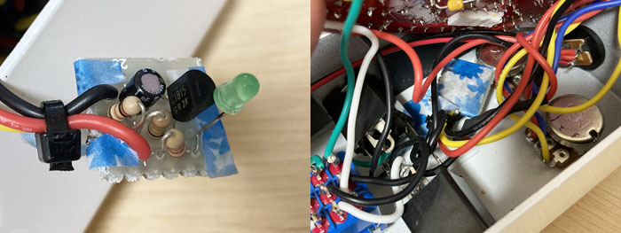
I made it with a universal board, put the green LED on the universal board, and inserted the LED head into the hole of the enclosure to fix it. Paper tape (blue flower) is attached to the back of the universal board so that it does not come into contact with other parts.
Blinking with an image like the one below, I can see the cycle well.
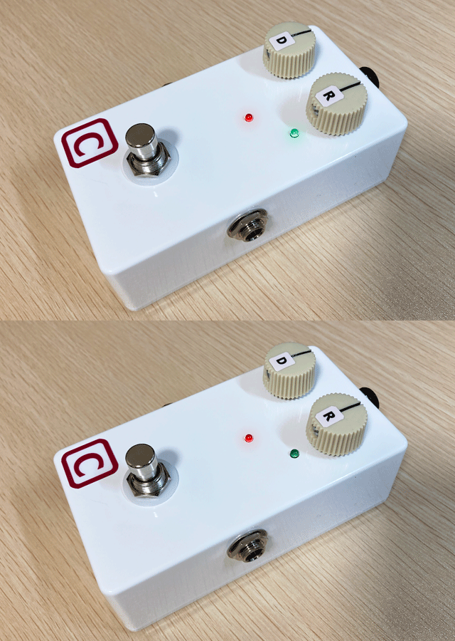
(This is a GIF animation created as an image. It is not an actual video.)
Language
Self-made
effect pedals
- Pedals list page
 Tool selection
VEMURAM Jan Ray
Xotic BB preamp
Klon Centaur
 Revived old Chorus
 MXR Envelop Filter
 BBD Analg Delay DM-3
 600ms Analog Delay
 Arduino Analog Delay
 BBD Analg Chorus CE-3
CMOS Octaver OC-2
 Riot using chip parts
 Original design noise gate
 EP & MICRO AMP duo
 Keeley 4 Knob Comp
 MXR Phase 90 MOD
 Keeley Blend Comp
 DM-3 longer delay time
 ISP Decimator V2164


