Keeley 4 Knob Comp using surface mount parts self-made report
Self-made Guitar Effect Pedals
Explore the articles to learn more about your favorite effect pedals.
|
Compressor making the rough performance sound good
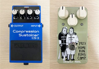 Speaking of compressors, I have also used the "Orange Squeezer" and "Dyna Comp" that were popular in fusion in the 1980s. I think these have a strong character as a pedal that emphasizes the attack of the picking sound. On the other hand, there is also a limiter-like compressor that adjusts the volume even for rough picking and cutting. I prefer this.
Recently, I have been using "BOSS CS-3" and "HOME RUN KING COMP".
So, as one of the pedals I haven't made yet, I tried to make my own "Keeley 4 Knob Compressor", which is a representative of ROSS-ish compressors with a wide range of sound creation.
Obtaining the schematic
Since the Keeley 4 Knob Comp is an old pedal, there are multiple schematics on the internet. I tried to get some, but there are some parts with slightly different constants. However, since it is almost the same circuit, it seems to be highly reliable.
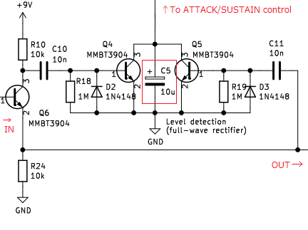
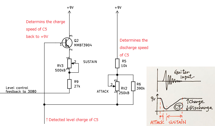
"CA3080" is used in most compressors. Level detection is performed from the signal (Pin 6) output from this chip, and feedback control is performed to return the level signal accumulated as an electric charge in the electrolytic capacitor (C5) to the volume control pin (Pin 5) of this chip. The circuit configuration is an orthodox circuit. The feedback part of the detected level contains pots that change the attack and sustain.
I made it with surface mount components this time, but especially for capacitors, there are constants that are not available for surface mount components, so I changed them to similar constants in consideration of the effects.
Create PCBs for surface mount components
33mmx38mm size surface mount PCB
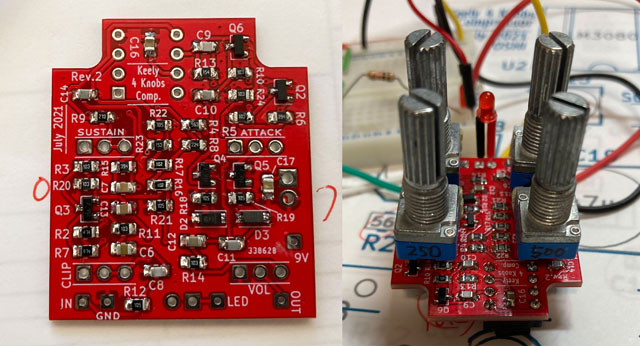
This is my 4th mini-sized effector self-made. The Keeley 4 Knob Comp has a relatively large number of parts, but this time I made a 33mmx38mm surface-mounted printed circuit board to put it in a mini-sized enclosure.
4 pots directly attached to the board
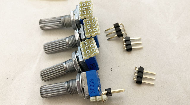
This comp has 4 pots. I wanted to attach the pots directly to the board to fix the board, but I couldn't buy a convenient pot. There are several pots for PCB mounting on the market, but there are few types that can be tightened with nuts, and most of them require a large hole in the enclosure to expose only the shaft of the knob without any nut.
Also, regarding the size, in order to fit in the mini size enclosure (HAMMOND 1590A), the width must be 15 mm or less.
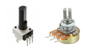
The left is for the board, but the nut cannot be tightened
The right is too big for a mini size effector
Finally, it was processed as shown in the photo below. The pins are for mounting on the board, but they are mounted horizontally on the board, and the orientation of the pins is different. Therefore, I used a universal board and an L-shaped pin header so that it could be mounted vertically on the board.
Designed PCB with KiCAD
The printed circuit board was designed using "KiCAD". The procedure is as follows.
1) Enter the circuit in the schematic editor
2) Select and assign footprints (actual part shapes) to all parts in the circuit diagram
3) Load the parts and connection information (netlist) into the board editor.
4) Enter the board outline of 33mmx38mm
5) Place the loaded components on the board so that the wiring is as short as possible while looking at the circuit diagram. At that time, the tall parts are placed on the front side, and the chip resistors / capacitors are placed on the back side.
6) Connect the power supply line (9V, Vref) on the front side.
7) Perform other wiring on the back side
8) Fill the remaining areas on both sides so that GND can be connected.
I used "2012" size for the chip parts, and made it by specifying the footprint of a large pad (the part where the parts are soldered) so that hand soldering is possible. If the part is not in the library, you can create it by modifying the shape of an existing part using the Footprint Editor.
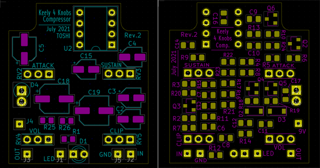
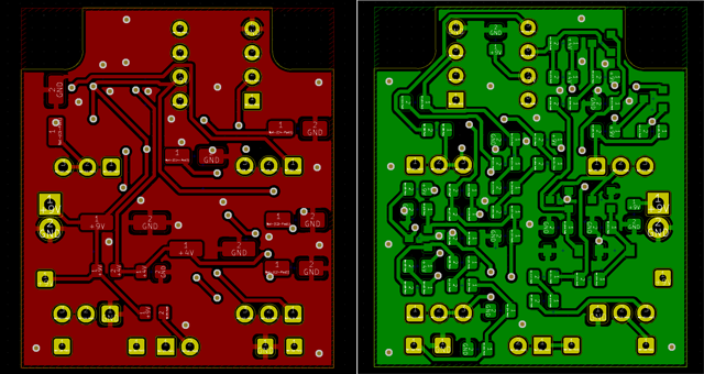
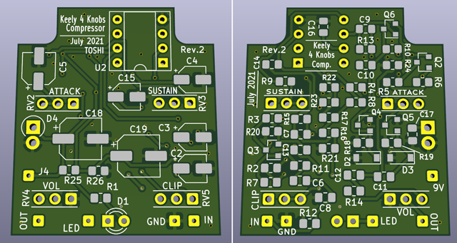
The point that requires special attention is the position of the terminal of the pot to be directly attached. It is necessary to determine the position of the pot terminal (L-shaped pin header) hole on the PCB based on the hole position to be drilled in the enclosure. If this position is wrong, it will not be attached to the enclosure, so I designed the distance of the hole position with KiCAD and carefully determined it. The same applies to LEDs.
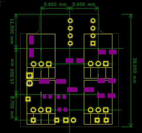
Another point to note is the direction of rotation of the pot. With wire connection, even if the rotation direction is wrong, you can correct it by connecting pins 1 and 3 in reverse. However, this time, the lead of the pot is directly attached to the board, so if the direction of rotation is wrong, it cannot be corrected. I decided the order of the holes in the PCB after confirming that it changed significantly when turned to the right.
KiCad PCB design data
The PCB data created using "KiCad (Windows 64-bit) Version: (6.0.4), release build" is provided. The ZIP file contains the schematic, board design data, and original component data. Please read the terms of use and disclaimer in the attached "readme.pdf" before using this data.
Order from Fusion PCB
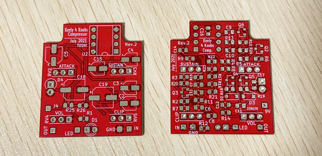
As usual, I created Gerber data, packed it in a ZIP, and placed an order from the Fusion PCB site. I received the PCB I ordered in about two weeks. FusionPCB has a slower delivery time than other board manufacturing services, but the quality of the PCB finish is high and stable. I still can't believe this PCB can be manufactured for $ 5.
Mount chip components on the board
Purchase of chip parts
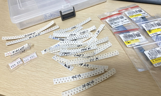
This is the third time to make a surface-mounted board. I have extra chip resistors and capacitors from the previous production, so I didn't have to buy a new one. I purchased additional constants and semiconductors that I don't have.
There is a sales unit for chip parts, and you can purchase chip resistors from about 20 pieces and chip capacitors from about 10 pieces. If you make your own effector many times, you will be able to use the parts you already have.
Soldering chip parts
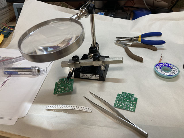
The surface mount components are really small and I used tweezers to solder them. I used a stand loupe to implement it because of my presbyopia.
Mounting pots to PCB
The pot was attached by inserting the lead extended by the universal board and the L-shaped pin header into the board. The distance between the pot and the PCB was determined so that the tall electrolytic capacitor mounted on the surface would not pop out of the lid when attached to the enclosure.
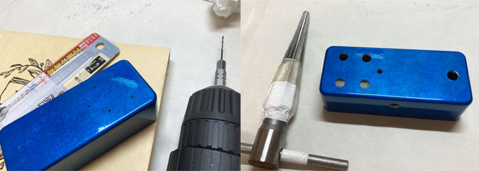
Drilling the enclosure
This time, the pot and LED are directly attached to the PCB, so the hole position of the enclosure must be drilled with millimeter accuracy. I used KiCad to draw the relative position of each part on the PCB and applied it to the hole position of the enclosure.
Here's how to use an electric hand drill to drill a hole in the correct position. Even if it is troublesome, you can make a hole at the correct position.
1) First, use a sharp drill or a screwdriver to dent the center of the hole position.
2) Make a hole by applying the tip of a 1.2 mm drill to the hole position in 1).
3) Next, widen the hole with a 3mm drill around this hole.
4) Further widen the hole with a 6 mm drill
5) With a taper reamer, widen the hole according to the hole diameter of each part.
One thing to keep in mind when drilling with a hand drill is not to push the tip of the drill during drilling. The 1.2mm drill can easily break if unnecessary force is applied. Also, in the case of a 6 mm drill, the groove of the drill will bite into the enclosure and the enclosure will rotate together dangerously.
Rather than pushing the drill to make a hole, I think it's more like shaving the enclosure lightly with the tip of the drill and gradually expanding the hole.
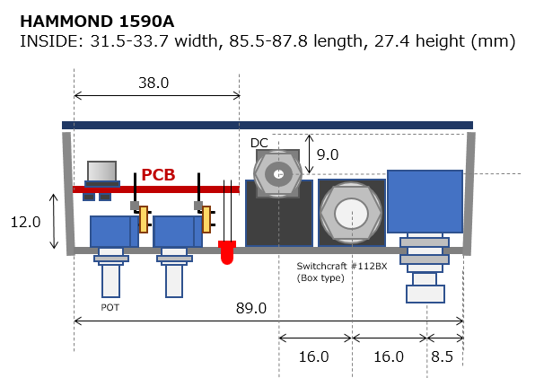
Placement in enclosure
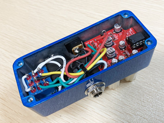
Below is an image of the parts and PCBs in the enclosure. I made holes to match this image.
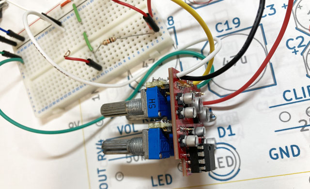
Check operation
Before incorporating it into the enclosure, I checked the operation with only the PCB. As usual, I generated a sine wave with free software on the PC and input the signal from the audio i / o (steinburg UR22mkII) to the PCB.
By inserting the wire from the PCB into the breadboard, I / O of the signal and connection of the battery were done.
Bad soldering mistake
When I first turned it on, there was no signal output. I followed the signal with a small oscilloscope I bought for $ 50, but the signal was cut off somewhere in the level detection circuit. A pot is directly attached to the board, and chip parts are attached under this pot. Connecting the oscilloscope probe was a tough task for me with presbyopia.
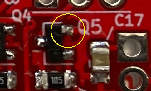
When I magnified the PCB with the iPhone camera and examined it, there was a solder defect in one pin of the chip transistor, and the solder did not flow to the pad. After fixing this, it worked fine.
Sound output characteristics
This compressor has four pots with variable attack and release. There is also a pot (CLIP) that can change the input level to the CA3080. Raising the CLIP will result in aggressive compression, and raising the sustain will change the length of the note. It is difficult to adjust, but the sound output can be finely adjusted according to the single coil or humbucker.
My impression is that the sound is more chunky than the BOSS CS-3.
In general, I think the reason why the sound feels chunky is "lowering the high range + increasing distortion". These keeley 4 knobs may be a little distorted. The Keeley C4 has a knob called "clip" that allows you to change the input level to the compressor circuit. The designer may be aware of the distortion, as he calls it "clip" instead of "input level".
With a low gain, crunch distortion pedal like Jan Ray, the distortion is less noticeable in the band, the level is kept constant, and the cutting sound comes forward (listeners can hear it properly). It may be better to use this "clip" adjustment to slightly distort and also obtain sustain in the compressor circuit.
Sound sample
This is a sample when playing a chord with a clean tone. I like the natural sound, so I'm assuming that it will be placed at the entrance of the pedal board and always on.
The same phrase will be played twice. The first half is OFF and the second half is ON. You can hear that the cutting level is constant and the final decay sound is extended. The attack is not emphasized, and the sound is like a limiter. A light reverb is applied in the DAW.
![]() Sample rhythm guitar (MP3)
Sample rhythm guitar (MP3)
The recording environment is:
Guitar (Strato, single mid pickup) -> Self-made Keeley comp -> MOOER Preamp006 (Fender blues deluxe clean, cabinet ON) -> UR22mkII -> DAW (Studio One)
Completed by incorporating in the enclosure
Create an original sticker
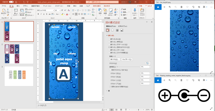
This time I used a blue-painted enclosure. I wanted to make it look like a commercial product, so I put a sticker on the top of the enclosure. I printed a design image made with PowerPoint on a sticker paper with an inkjet printer and cut it out. Holes such as pots are cut out with a cutter according to the holes after sticking a sticker on the enclosure.
I searched for and designed a graphic of water drops. I named it "patet aqua comp" (Latin) with the image of a natural sound like water. The "A" of aqua is used as the initial.
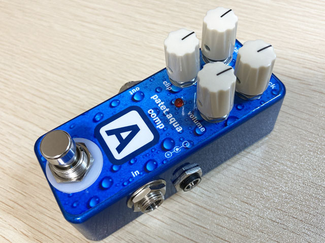
Beautiful "patet aqua comp" completed
The sticker on the top is nice. I am very satisfied with the completed self-made comp.
Language
Self-made
effect pedals
- Pedals list page
 Tool selection
VEMURAM Jan Ray
Xotic BB preamp
Klon Centaur
 Revived old Chorus
 MXR Envelop Filter
 BBD Analg Delay DM-3
 600ms Analog Delay
 Arduino Analog Delay
 BBD Analg Chorus CE-3
CMOS Octaver OC-2
 Riot using chip parts
 Original design noise gate
 EP & MICRO AMP duo
 Keeley 4 Knob Comp
 MXR Phase 90 MOD
 Keeley Blend Comp
 DM-3 longer delay time
 ISP Decimator V2164


