Original design noise gate pedal using surface mount chip parts
Self-made Guitar Effect Pedals
Explore the articles to learn more about your favorite effect pedals.
|
Originally designed noise gate circuit using JFET
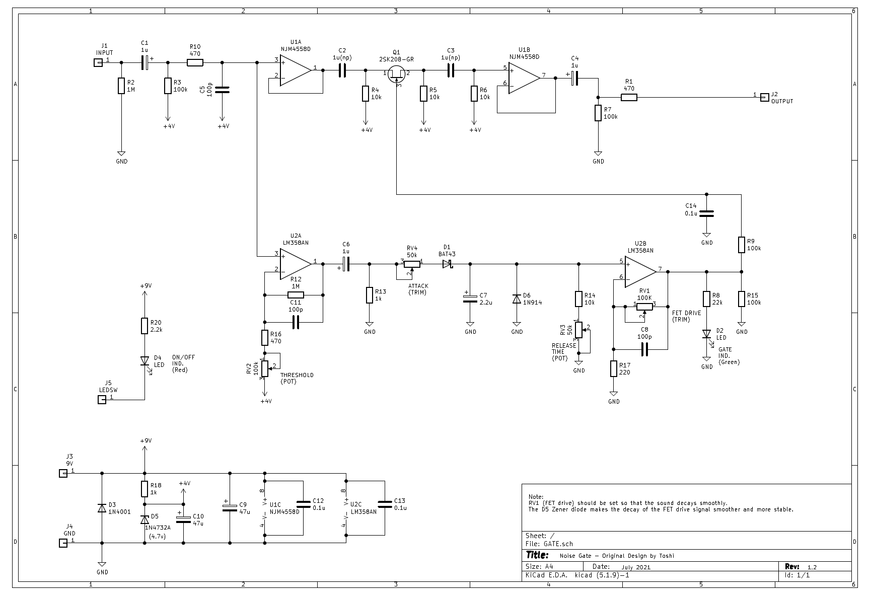
I designed a noise gate pedal, one of the pedals I haven't made yet. The noise gate requires a circuit (VCA = Voltage Controlled Amplifier) that automatically opens when there is a signal and closes when there is no signal. This time, I tried using the simplest J-FET.
I often see circuit diagrams made by someone, but I have never thought about it myself. This is the first time that I made it myself by referring to the circuit diagrams of various pedals.
Signal processing block diagram
I used a JFET to switch the signal on and off. The operating principle of the JFET is very simple, and the voltage applied to the GATE can control the current flowing between the SOURCE and DRAIN. In other words, when a high voltage is applied to the GATE, the SOURCE-DRAIN will conduct, and when the GATE voltage is lowered, the SOURCE-DRAIN will close.
Therefore, the level of the input signal is converted to a voltage, and this is put into the GATE of the JFET, so that a circuit that turns on the switch only when the signal is input can be created.
This time, I used a JFET called "2SK30A", which is often used in audio circuits because of its good sound quality. This FET is used in the electronic switch of the BOSS's pedals.
I wrote the block diagram. The circuit that converts the level of the input signal to voltage is a simple one that uses diodes, resistors, and capacitors. The principle is to store the input signal in a capacitor and convert it to a DC voltage. At this time, the current of the input signal is one-way due to the diode, and the electric charge is accumulated in the capacitor only when the input signal becomes higher than the electric charge of the capacitor. A large resistor is attached to the capacitor, and the accumulated charge is slowly discharged to GND. As a result, the signal turns off smoothly as it attenuates.
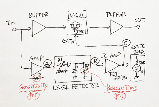
In order to turn on the FET fully, it is necessary to apply the same level of voltage as the power supply voltage, so the DC level is raised by the DC operational amplifier.

DC AMP signal image driving FET
DC AMP to raise the detected level
Since the charge (DC voltage level) stored in the capacitor is small to give to the GATE of the FET, it is necessary to amplify this voltage level so that the FET can be controlled. The DC level is amplified simply by using an operational amplifier.
At this time, note that general operational amplifiers (4558, etc.) have a phenomenon called "output inversion". This is a phenomenon in which the output reverses to the voltage in the opposite direction when an input near or exceeds the negative power supply (-V) or positive power supply (+ V) is given. Such an operational amplifier cannot be used to amplify the DC level between GND and the power supply voltage like this time.
For DC AMP, it is necessary to use a "single power supply operational amplifier" that does not cause output inversion even if a voltage close to GND is input. I used the typical "LM358" for this purpose.
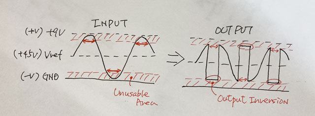
General operational amplifier that causes "output inversion" that cannot be used for DC amplifiers
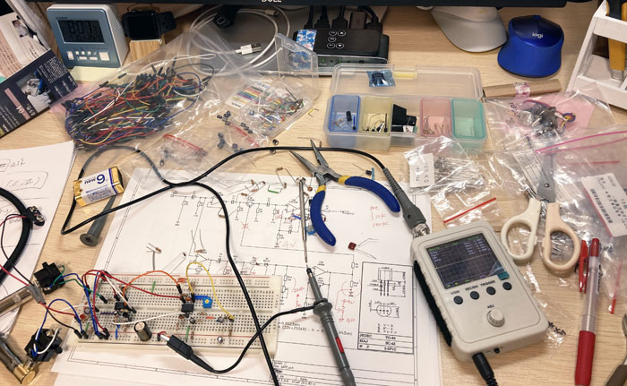
Prototype on breadboard
I bought a breadboard for the first time to check the operation of the circuit and adjust the constants. This is for building circuits by inserting component leads into holes in the board for electronic work and prototyping. I decided the constants while checking the signal condition with a portable digital oscilloscope purchased for $50.
However, breadboards do not have a shielding effect because the parts are exposed. If you actually connect the output to an amplifier and make a sound, the noise will be large. I think it would be improved if the circuit was actually placed on a universal board or printed circuit board and put in an aluminum enclosure, but the noise level cannot be evaluated on a breadboard.
The quality of a noise gate depends on whether the gate closes smoothly as the sound of the guitar decays. Bad reviews of commercial noise gates include "sudden cuts" and "unnatural sound attenuation". This adjustment is difficult because it is a simple circuit. I managed to adjust the constants so that it worked.
Mini size pedal using surface mount chip parts
Design surface mount PCB
This time, as with the previous "Suhr Riot Clone" production, I created a PCB on which surface mount chip components can be mounted. I designed a double-sided PCB using "KiCAD" and placed an order with "Fusion PCB" in China, which manufactures PCBs in less than two weeks. Since I received a $5 coupon, the production cost was zero this time as well, and I only had to pay the DHL shipping fee ($15).
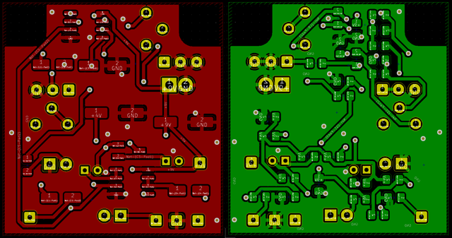
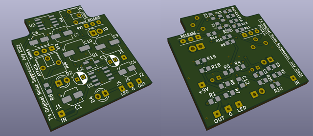
Board designed with KiCAD (trace diagram, 3D image)
KiCad PCB design data
The PCB data created using "KiCad (Windows 64-bit) Version: (6.0.4), release build" is provided. The ZIP file contains the schematic, board design data, and original component data. Please read the terms of use and disclaimer in the attached "readme.pdf" before using this data.
Purchase of chip parts
There are few stores that sell surface-mounted chip parts for personal work, and there is a minimum purchase unit of 20 to 100 pieces, so it is difficult to purchase cheaply. I bought them separately for each type of parts from the four shops I usually use.
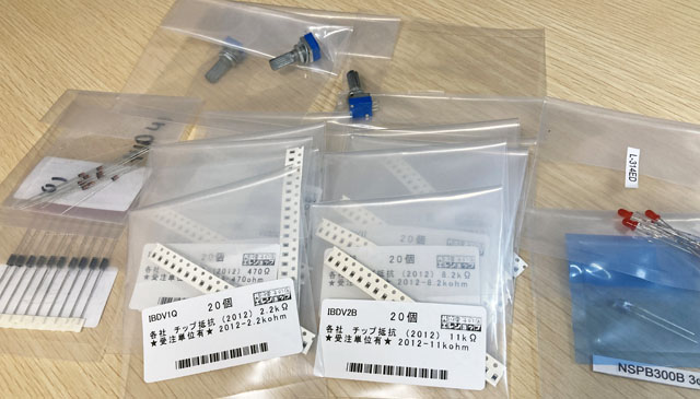
Board arrival, component mounting started
Purchase a workbench with a magnifying glass
The board I ordered has arrived from Fusion PCB. It took 10 days from ordering. I immediately started mounting the parts. When I made Riot last time, the surface mounting chip parts were so small that it was difficult for me with presbyopia to mount them, so I bought a workbench with a magnifying glass this time. I think the magnification is less than double. Even when I looked closer to the board through the lens, it was easy for me with presbyopia to focus, and the lens was large enough to be seen with both eyes, so it was comfortable.
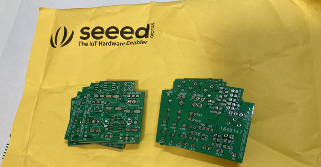
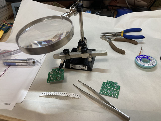
I steadily attached the parts with tweezers and completed the mounting in about 3 hours.
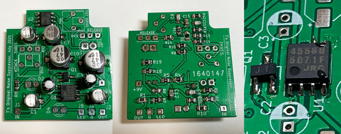
Check operation
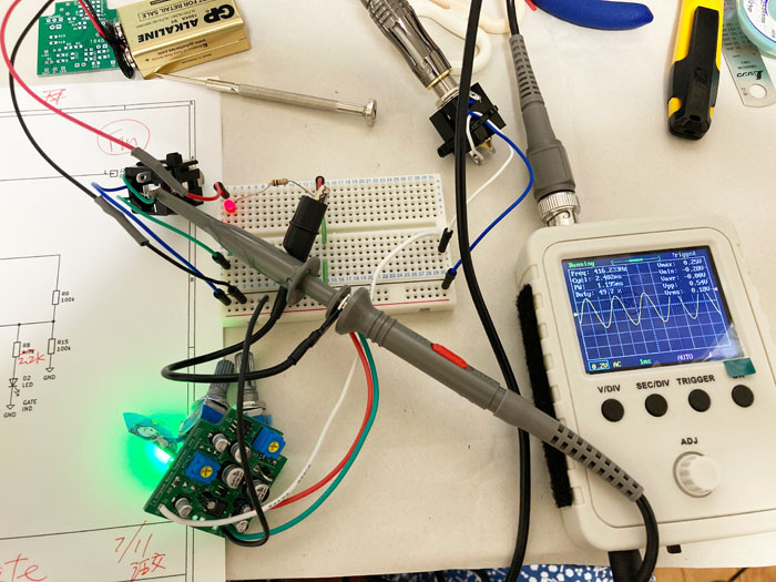
This time, before incorporating it into the enclosure, I checked the operation with only the board. As usual, I generated a sine wave with free software on my PC and input the signal from the audio i/o (steinburg UR22mkII) to the board.
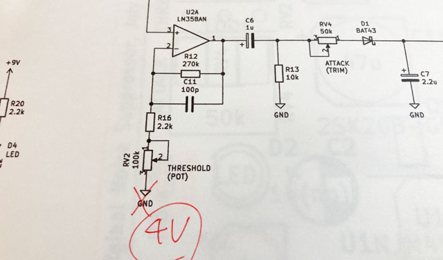
Circuit diagram error
I tried plugging in the power supply, but unfortunately it didn't work and there was no signal at the output. The green LED indicating the GATE status was not lit at all.
I followed the circuit. The signal came to the input (pin 3) of the first stage operational amplifier (LM358) that creates the level signal, but the signal did not come out from the output (pin 1). The output was equal to the power voltage.
When I reviewed the circuit diagram, the connection destination of the operational amplifier (-) was wrongly set to GND. Probably, it seems that I made a mistake when I finished the design on the breadboard and wrote the circuit diagram. I reconnected this line to the correct + 4V (reference voltage).
Fine-tune the constant while turning the pod
After correcting the above wiring mistake, I was able to confirm the same operation as the breadboard. There was no noise I was worried about on the breadboard and the SN was good.
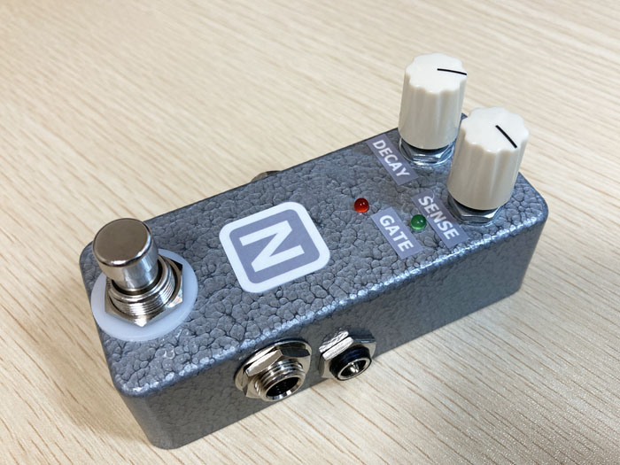
This pedal has two pods, a "SENSE" that adjusts the sensitivity of the guitar input and a "DECAY" that determines the length of time the gate closes. For "SENSE", the gain was insufficient for a single coil with a small output, so the constant was adjusted so that the gain of the first stage operational amplifier (LM358) would increase.
Drilling enclosure
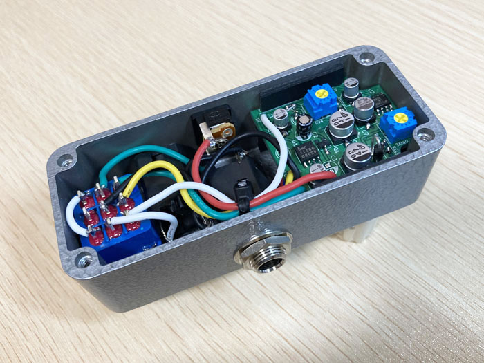
For this enclosure, I used the same HAMMOND 1590A that I used when I made Riot. The hole positions of the switch, jacks, and pots are the same as Riot. Since the LEDs are directly attached to the board, they were processed while paying attention to the position.
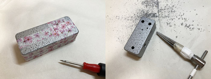
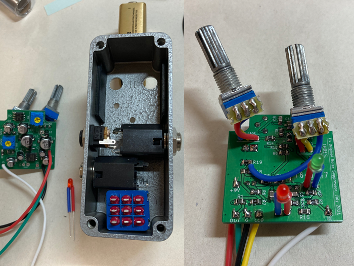
Placement of parts
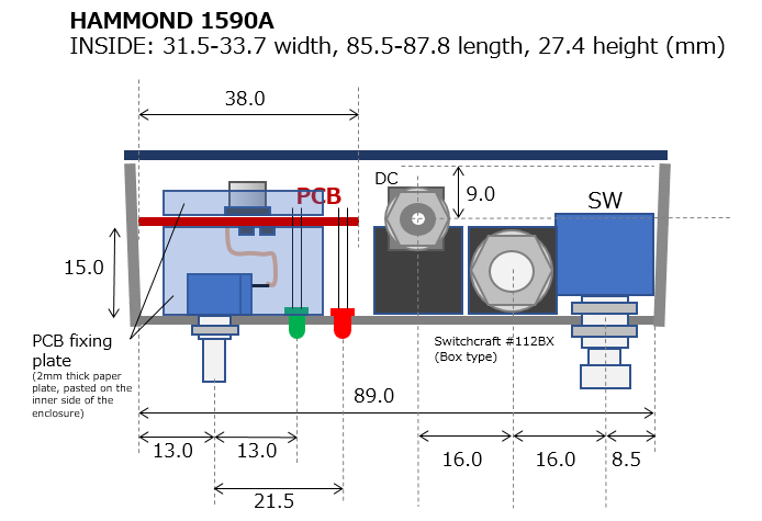
The placement of the parts inside the small enclosure assumed the cross section below. Since the LED is directly attached to the board, holes are drilled while paying attention to the position. The PCB is fixed by sticking 2 mm thick cardboard on the inside of the enclosure.
Sound samples
You can listen to 4 samples. The same phrase will be played twice. The noise gate is OFF first, and then the noise gate is ON.
In the case of the third long tone phrase, it seems that the sound is cut off in the middle of attenuation, but I think that there is no problem when using it for live performances.
It's completely silent while you're not playing, so you'll hear effects such as delay and reverb clearly, as in the fourth sample.
When using a high gain distortion like Riot with a single coil, it was difficult to use because of noise, but when this noise gate is inserted, the distortion sound is cut out, it sounds like a lump, it becomes more powerful, and the volume I feel like it has gone up.
![]() Sample: Short cut sample, DECAY longer (MP3)
Sample: Short cut sample, DECAY longer (MP3)
![]() Sample: Solo, long tone. (MP3)
Sample: Solo, long tone. (MP3)
![]() Sample: Solo. With a repeating long delay (MP3)
Sample: Solo. With a repeating long delay (MP3)
The recording environment is:
Fender Stratocaster (rear single) -> Self-made noise gate -> Self-made Riot -> MOOER Preamp006 (Fender blues deluxe clean, cabinet ON) -> UR22mkII -> DAW (Studio One)
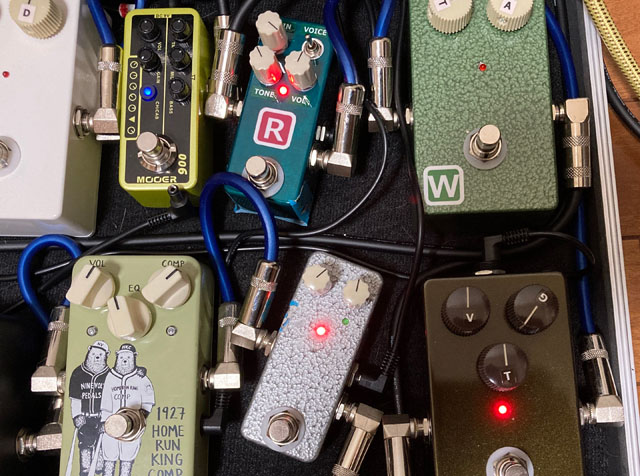
Completion of the original design noise gate!
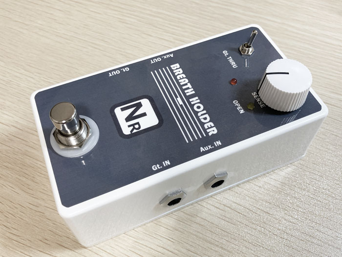
The color of the enclosure this time is "silver hammer tone" with a silver mesh coating. I put the stickers of the knob name and the initial mark of "N".
[Addition] Subsequent improvements
In order to close the FET gate smoothly, I changed the circuit that creates the reference voltage of the operational amplifier from a voltage divider circuit using a resistor to a stabilizing circuit using a Zener diode (D5). The reference of the first stage LM356 has become stable, and as a result, the accuracy of the level signal (robustness against noise) has improved. The sound of closing the gate used to be fluttering, but it has almost disappeared and is now smoother.
Also, I put a diode (D6) in the para of the electrolytic capacitor (C7) that stores the charge of the level signal. Normally, in this circuit, the charge level of C7 does not swing negatively, so the diode should have no effect. I feel that the closing behavior of the gate when the release time is shortened has become smoother.
I realized that such improvements in analog circuits can be changed by accumulating small things. Also, if I come up with an idea, I'll give it a try.
[Addition] Bought and tried "Rowin NOISE GATE" made in China
Makes a great sound!
There are many mini-sized effectors made in China on the market, including a noise gate. A copy of NOISE KILLER made by a company called MOOER is sold under three brands: Donner, Rowin, and NEEWER. You can buy these for $ 30.
So I bought a noise gate pedal from a brand called Rowin and tried it. As soon as I arrived, I exchanged it for my own NOISE GATE on the pedal board and tried to make a sound.
In conclusion, the sound is great. The most difficult thing about NOISE GATE is how to turn off the sound just before it turns off, but it's exquisite and doesn't feel strange at all. Furthermore, regarding the picking sound, compared to when NOISE GATE is turned off, the sound when the pick hits the strings is certainly softer and different, but I think it depends on how you play.
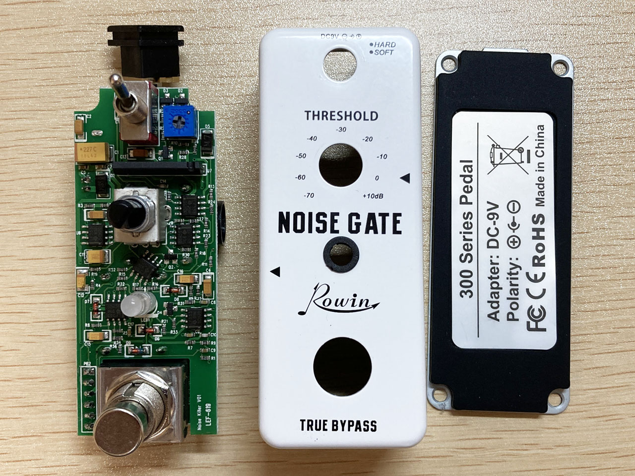
Disassembled Rowin NOISE GATE and observed the inside
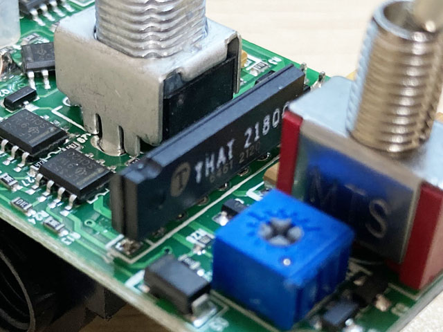
I disassembled and observed the PCB inside. Six LF353 operational amplifiers are used, and a high-performance VCA called THAT2180 is used for the gate control part. It's more like an "intelligent automatic volume" than a "noise gate".
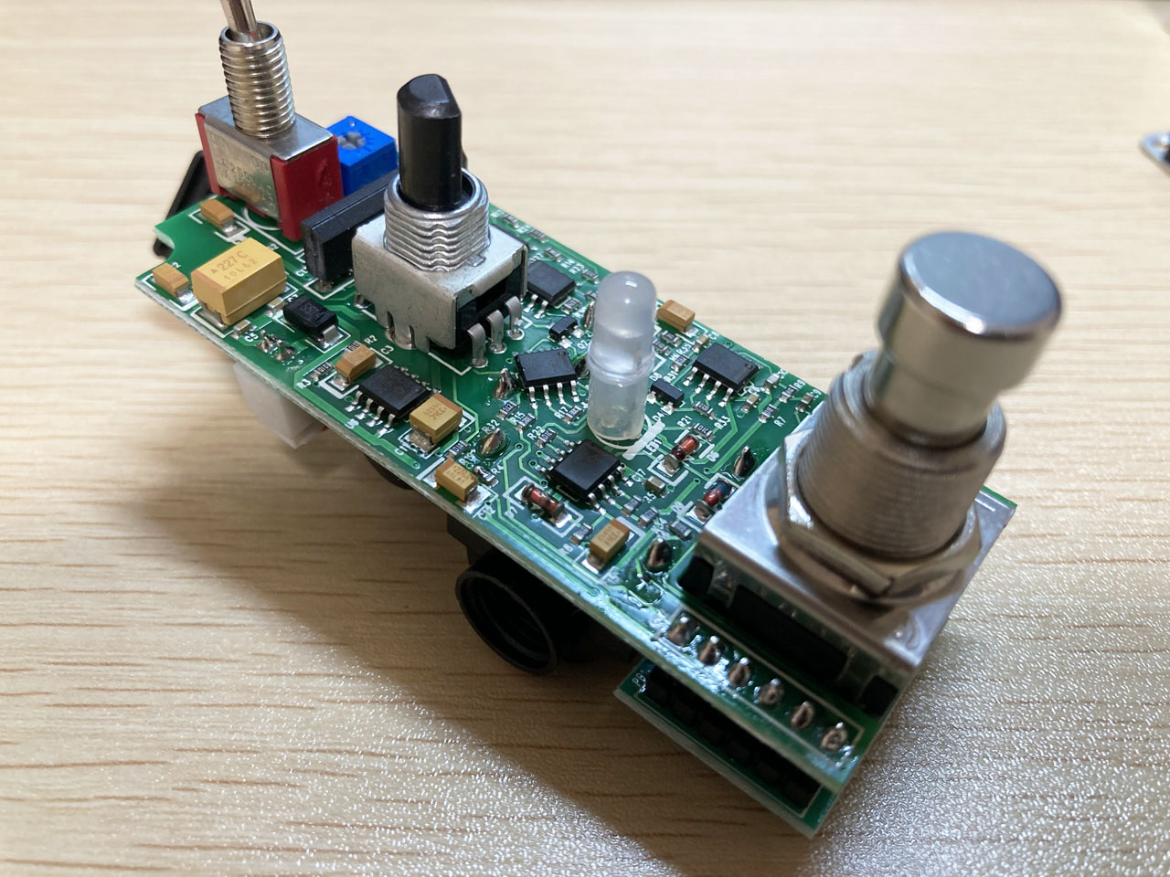
The Rowin NOISE GATE circuit is probably an ISP Decimator ?!
It is said among effector geeks that this circuit seems to be the same as MOOER. The shape of the enclosure, the switch, the LED, and the position of the pot are the same, so it makes me wonder if it is an OEM.
Looking at the circuit diagram of "ISP Deimator", which is a famous noise gate, "THAT 2181" is used and it is the same VCA as Rowin. The schematic has more than 10 op amp triangle marks on it, which matches the number of LF353s on Rowin's PCB. Perhaps this Chinese noise gate is based on Decimator.
Analog ones are easy to copy. I think the first design of this circuit was probably a daunting task.
Anyway, it is cheap and high performance, so those who are interested should buy it.
ISP Technologies White Paper
A white paper from ISP Technologies says that Decimator uses expander technology rather than a gate (ON/OFF) switch that responds to the level of input. When the level becomes lower than the threshold, the volume is sharply turned down (increasing the expander ratio) instead of closing the gate. As a result, it seems that the sound is produced so that it disappears fluffy instead of being cut off.
In addition, a technology called "time vector processing" is used for the part that detects the volume level of the guitar. It seems that the level envelope is smoothed so that the phenomenon that the level changes flutteringly due to noise does not occur near the threshold.
I am curious about how these are realized by analog circuits of operational amplifiers and a VCA chip.
Added LED to display the ON / OFF status of the gate
Because I want to visually check anything, I am observing the circuit board to see if the ON / OFF of the gate can be displayed by LED in this Rowin. Looking around the VCA chip of the THAT2180, it seems that this Rowin is very similar to the circuit of the ISP Decimater. The level detection part has exactly the same resistance constants.
Since pin 2 of the THAT2180 is the signal input for VCA control, I think that the LED can be turned on using the signal here (the output of LF353, the red circle in the photo below).
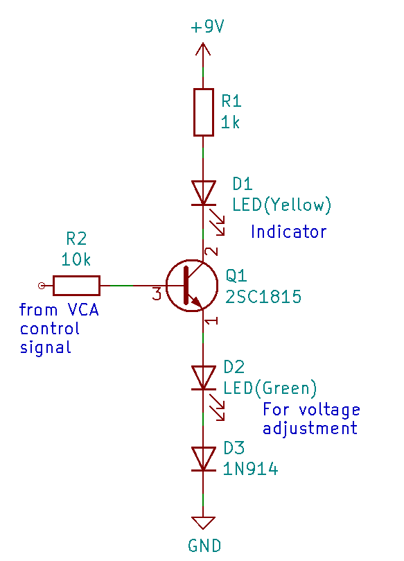
When observed with an oscilloscope, the VCA control signal (output of LF353) changes to about 0.8V when the gate is off and about 4.5V when the gate is on. Therefore, I would like to consider a circuit in which the LED starts to turn on at about 2V and turns on completely at 4V.
I tried to turn on the LED with the circuit below. An LED (Green) and a diode are inserted on the emitter side of the transistor in order to adjust the lighting start level of the LED (Yellow) using the forward voltage (VF). The LED forward voltage is VF = 1.8 to 2.6V, and the 1N914 is VF = 1.0V. Since the sound actually starts to be heard when the threshold is about -40dB, I adjusted the number of LEDs and 1N914 so that it starts to turn on from this level. If you want to start turning on later, you can add another 1N914.
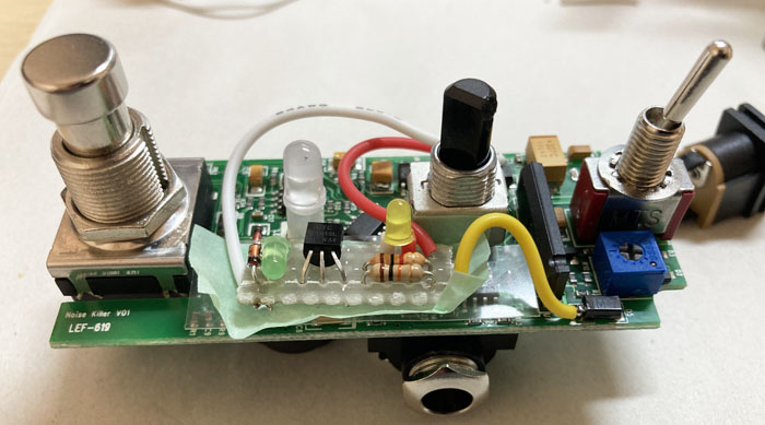
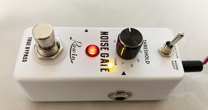
I will keep my own noise gate in storage, and I will put this Rowin noise gate in the pedal board and use it for a while.
YouTube video modifying Decimator release time
Nick Leonard who does mix tutorials, plugin demos, and DIY recording projects contacted. He was looking at release times for noise gate pedals for use in heavy metal. He thought that any manufacturer's noise gate has a slow release time (gate closing time) for use in heavy metal, and he was looking for ways to shorten the release time.
I suggested modifications based on the schematics on the La Revolution Deux, and then he actually applied the modifications to a Chinese Decimator clone pedal and was able to get the desired release time.
Check out the YouTube video below. This page has been featured!
[NEW!] Noise reduction pedal self-made report based on ISP Decimator
I tried to make a noise reduction pedal by using another VCA chip V2164 (Coolaudio) based on the circuit of the noise gate pedal "ISP Decimator". Please see the production article from the link below.
This ISP mod pedal is more complecated than my origibnal one, but you will be able to get more natural or practical noise reduction.
Language
Self-made
effect pedals
- Pedals list page
 Tool selection
VEMURAM Jan Ray
Xotic BB preamp
Klon Centaur
 Revived old Chorus
 MXR Envelop Filter
 BBD Analg Delay DM-3
 600ms Analog Delay
 Arduino Analog Delay
 BBD Analg Chorus CE-3
CMOS Octaver OC-2
 Riot using chip parts
 Original design noise gate
 EP & MICRO AMP duo
 Keeley 4 Knob Comp
 MXR Phase 90 MOD
 Keeley Blend Comp
 DM-3 longer delay time
 ISP Decimator V2164


