Self-made overdrive pedal Klon Centaur clone
Self-made Guitar Effect Pedals
Explore the articles to learn more about your favorite effect pedals.
|
King of overdrive KLON Centaur
Centaur is a guitar overdrive pedal made in Australia. It is used by many guitarists all over the world. Its sound is chunky and clean, so it is called the king of overdrive. However it's very expensive and sold for over US $1000. Wow!!
Therefore, I tried to make my own using the circuit diagram and board layout posted on the Internet. This page is a report from the start to the completion of my own work.
Schematic and board trace layout
 The real Centaur hides the components, circuit constants and component types on the board with glue. Therefore, only two types of schematic can be found probably because it is difficult to make a circuit diagram from the actual circuit board.
Schematic 1: Some parts may be missing. The number of parts is slightly small.
Schematic 2: It is extracted from the real serial 698 and seems reliable.
This time I used the Schematic 2. However, there is no way to confirm that this is the same as the real part constant. Accrding to the articles of self-made Centaur, they say that almost the same sound will be produced with the schematic.
I hand-wired it by point-to-point without any printed circuit board. However in 2021 now, printed circuit boards are sold from various shops. If you google with "Centaur PCB", you will find a lot easily.
Circuit configuration and components
The Centaur circuit has a unique configuration. The distortion sound clipped by the germanium diode (IN34) and the original sound are mixed by the adder circuit of the operational amplifier. In addition, the sound filtered by CR which seems to be used to boost the midrange are further mixed. The distortion gain and this filter mix amount are controlled proportionally by the double potentiometer, and the mix amount decreases as the gain increases. These should be a double potentiometer. If they are independent, a feedback loop will occur when the gain is increased, causing oscillation.
The operational amplifier is a general low noise type (072CP). In addition, there are many special resistance constant values that carbon resistors do not have, so it is necessary to use metal film resistors which have a constant error of 1%.
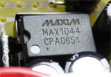 The special part is an IC called 'charge pump' that doubles the power voltage. One of the reasons Centaur's sound is clean and dynamic is due to the high voltage created by this charge pump IC. The operational amplifier used in the final stage adder circuit is driven by +18V and -9V. It has a dynamic range three times of a normal +9V circuit. Even when the peak signal comes, the sound can be transmitted straight to the amplifier without clipping. This seems to create the characteristic of Centaur's sound.
I found a site that explains the Centaur circuit in detail. If you are familiar with electronic circuits, please refer to that.
Purchasing parts
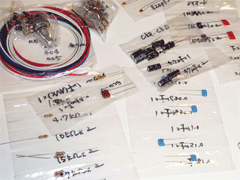 I purchased all parts from the Japanese mail order shop on the Internet, Ginga Drops. They supplies all the electronic components, for effect pedals including special items such as charge pump ICs.
Ginga Drop's parts packing are very kind, and all the constants are handwritten on the packing bag. It is so appreciated.
Currently in 2021, Ginga Drop has been closed. If you are a resident in Japan, I recommend another good shop "GarrettAudio".
Manually wired circuit board
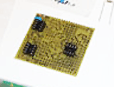 I wired on an universal circuit board by point-to-point manual wiring. I like hand wiring and have never made a printed circuit board. I know a printed circuit board is better for replacing parts for the MOD and making trial and error.
When wiring by point to point, I first write a trace on the surface of the board with a marker pen to make my work easier when comparing the board and the trace diagram alternately.
My hand-wiring is like: insert the component into the hole in the board, bend the remainder of the lead wire of the component with needle-nose pliers to create a trace, make a trace using the leads of the parts as much as possible. When the trace is terminated, cut the lead. Solder only the part where you need to connect the leads. This task is difficult to write, but it's easy to wire it once you get used.
Pay particular attention to the polarity of the electrolytic capacitors. In addition, one tantalum capacitor is used in Centaur. It is similar to non-polar ceramic capacitors, but note that tantalum has polarity.
The switch wiring can be true bypass, but the real Centaur is not true bypass. When the effect is turned off, the signal buffered by the input operational amplifier (072CP) is output. Since the impedance is lowered by the input buffer, it may be better for the connection of the effect pedals after Centaur. This time, I chose buffered bypass as same as real Centaur.
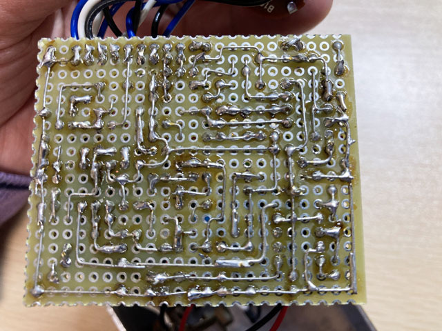
Check after board completion
When completing the board wiring, first check the voltage of the power supply with a tester. A tester is a must-have item. You can buy it for less than US $20. You don't need a high-end tester that has many functions. It is OK if it has the DC voltage measurement and continuity test functions.
The first thing to check is the voltage boosted by the charge pump IC. +V2 is about twice the battery voltage, and -V is the negative battery voltage. There is a possibility that it is short-circuited, so it is safer to use a battery than an AC adapter. If this is OK, let's check the sound output.
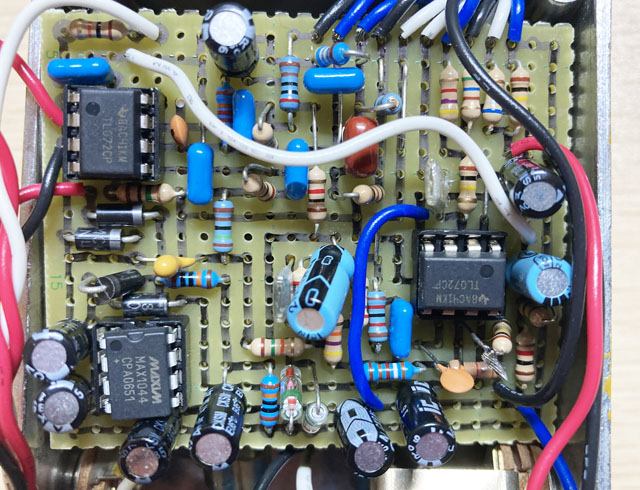
Sound output check
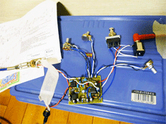 I checked the sound without incorporating it in the enclosure for the first trial. I taped it onto an insulated object, such as a cardboard or plastic case lid.
The orientation of the potentiometer is often mistaken. Check if it gets bigger when you turn it clockwise.
In my case, I made a mistake in the orientation of the tantalum capacitor (C16 in the circuit diagram). It was really difficult to find the mistake. The behavior was like that: after turning on the power, a sound was heard at first, but after 5 or 10 minutes, the output level gradually decreased, and finally it stopped at all. I guess that the DC component accumulated in C16 caused it to go out of dynamic range.
The only way to find mistakes is by staring at the layout diagram, schematics and board. If you don't like this, you should purchase a printed circuit board.
Overdrive sound can be changed by replacing the clipping diodes. If you attach a socket for the diodes, it will be easier to replace.
My impression of the sound is that it is straighter without roundness or muffled sound when setting the gain knob less than 9 o'clock. The sound when picking or hitting the frets is bright, and it is a very clean sound. It gives me the illusion that the sound of my Stratocaster itself has improved. Even if the GAIN knob is set to MAX, the distortion amount is about only half of SD-1.
My analysis of Centaur sound
Considering the circuit mechanism of Centaur, the sound from the guitar is transmitted to the amplifier without clipping in Centaur by the power supply range of 27V generated by the charge pump IC. In addition to that, I think that the distortion circuit in Centaur adds a unique color. Many people say that it does not distort much by itself, or that it is better to use it as a booster. I think the reviews make sense. It's really a clean and powerful overdrive pedal..
When GAIN is set to "0" and used as a clean booster, it not only raises the volume, but also adds brightness to the guitar sound and makes the sound more energetic. I feel that the sound comes out in front of the band.
If you raise GAIN above 9 o'clock, the sound character will change. The treble drops and distortion is added, resulting in a vintage overdrive sound. Even if the GAIN is full, it will not be distorted like a normal distortion pedal.
This is not a real Centaur, but I'm so satisfied.
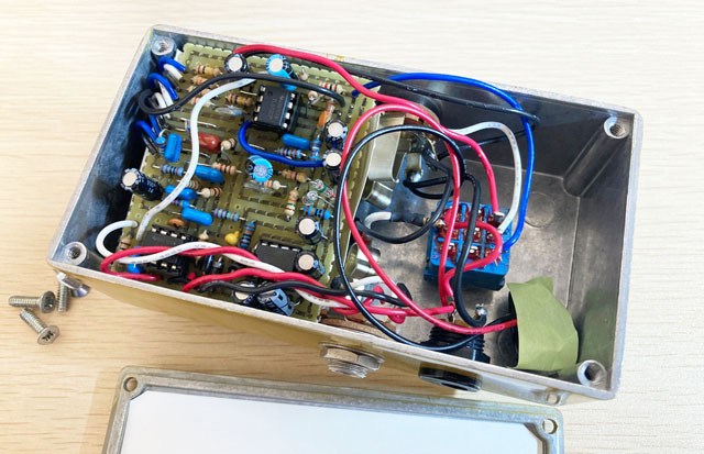
Put it in the enclosure and it's completed!
After checking, I put it in the enclosure and completed it! This time, I bought a aluminum enclosure painted in vintage yellow. It is a HAMMOND 1590N1 whose size is slightly larger than compact pedals such as MXR.
Sound samples
The same phrase will be played twice. The first half is OFF (buffered bypass) and the second half is ON.
Recording environment: Fender Stratocaster -> Self-made Centaur -> ZOOM G3X (Fender Twin Reverb clean simulation) -> UR22mkII -> DAW (Studio One)
![]() Gain 0, Chord (MP3) - Stratocaster halftone
Gain 0, Chord (MP3) - Stratocaster halftone
![]() Gain 0, Phrase (MP3) - Stratocaster front pickup
Gain 0, Phrase (MP3) - Stratocaster front pickup
![]() Gain Center(12 o'clock), Phrase (MP3) - Stratocaster front pickup
Gain Center(12 o'clock), Phrase (MP3) - Stratocaster front pickup
[Additional report] Tuner noise suppression
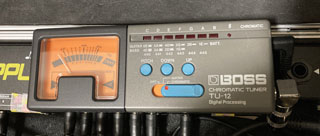 I noticed that some noise was added when the sound was decayed. I connected the signal like: Guitar -> Tuner -> My own Centaur -> Other effect pedals. Bypassing the tuner eliminates the noise, so I recognized that the tuner caused the noise. So, I added a THRU output to my own Centaur for the tuner connection.
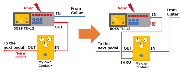
Tuner output addition
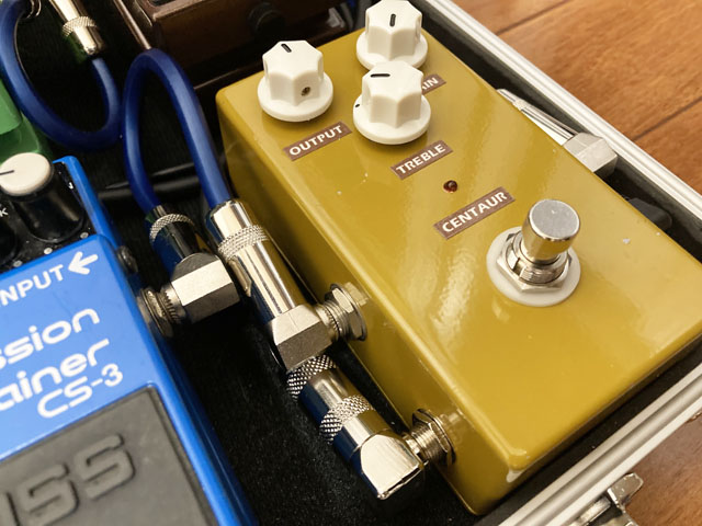
The problem with modifying my own Centaur is where to put the THRU output jack. Currently my own Centaur is put in the effect pedal board and it is used only with an AC adapter, so I changed the specification so that it does not use any battery and decided to attach the output jack to the battery space.
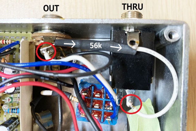
After the modification, the noise got smaller and the sound output improved significantly.
[Additional report] The second self-made Centaur
I'm happy with the Centaur I made above. One day I found out that the schematic I used when I made it has been updated. Therefore, I decided to make another one with the updated parts constant.
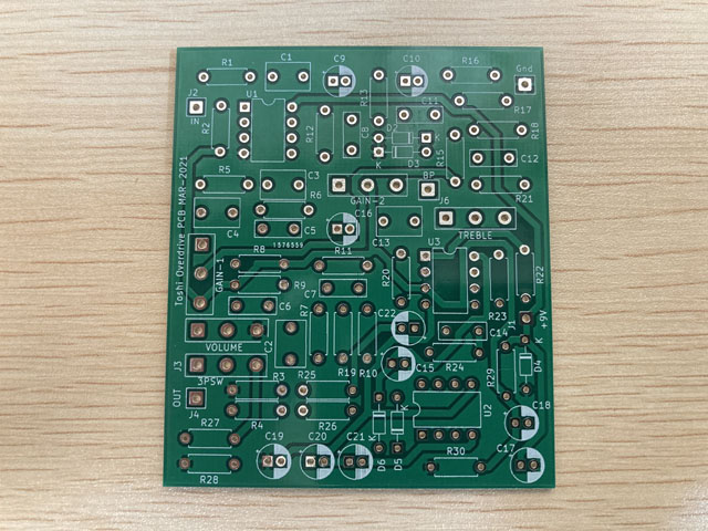
This time, I designed the printed circuit board myself and ordered it from "Fusion PCB" in Shenzhen, China. The board design was done using the freeware "KiCAD" for all processes. I input the circuit diagram, designed the two-layer circuit board, output the standardized board design data called "Gerber data", and sent it to the Fusion PCB.
The manufacturing fee is only $ 5 and DHL shipping costs $ 20, so the total is $ 25. Still, it's cheap enough that I can make a self-made board for $ 25, which generally costs hundreds of dollars. It arrived about a week after I sent the data.
The sad result
I implemented the components and tried it. I put this box in front of all the effect pedals and use it as a clean buffer to improve the sound of the guitar itself. Compared to the Centaur clone created last time, the impression of the sound is that the low range is increased, and the sound is chunkier.
However, unfortunately, the oscillation noise of the charge pump IC (noise that sounds around 10kHz) is larger than the previous work (point-to-point wiring). I tried to increase the capacity of the bypass capacitor of the power supply and add a multilayer ceramic capacitor, but I could not completely remove it. Probably, the IC layout of the designed board is bad, and noise is jumping from the charge pump IC to the audio line.
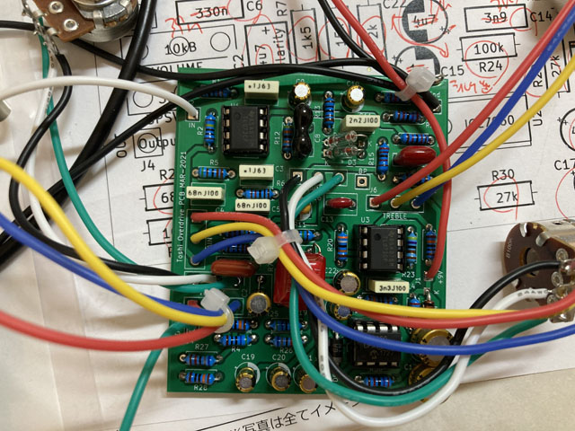
Removed the charge pump IC
Finally, I removed the charge pump IC from this self-made Centaur and made it a +9V specification Centaur. I am not connecting the Centaur directly to the amp, so I think that even a voltage of 1/3 of the actual specification (27V) will work just like other effect pedals. I unplugged the charge pump IC from the socket and shorted two parts of the circuit.
I put it in a gold enclosure (which looks brownish). I compared it with my first Centaur, and although there was almost no difference, but I feel that the Stratocaster sound is a little chunkier. Since the charge pump IC has been removed, the noise has been suppressed perfectly. When setting GAIN and LEVEL to MAX, some white noise is generated, but there is no problem in normal use.
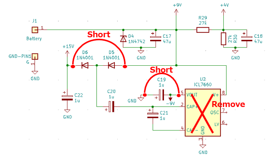
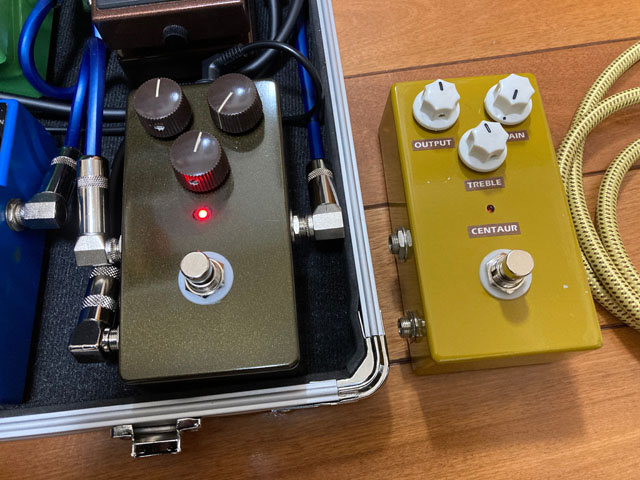
Replaced the previous made (yellow one) to the new one (brownish gold)
I've created a page about the tools you need to make your own effects pedals and the basics of how to make them. Please refer to it.
Language
Self-made
effect pedals
- Pedals list page
 Tool selection
VEMURAM Jan Ray
Xotic BB preamp
Klon Centaur
 Revived old Chorus
 MXR Envelop Filter
 BBD Analg Delay DM-3
 600ms Analog Delay
 Arduino Analog Delay
 BBD Analg Chorus CE-3
CMOS Octaver OC-2
 Riot using chip parts
 Original design noise gate
 EP & MICRO AMP duo
 Keeley 4 Knob Comp
 MXR Phase 90 MOD
 Keeley Blend Comp
 DM-3 longer delay time
 ISP Decimator V2164


