YAMAHA CH-01 Chorus:Revived from 30 years ago!
Self-made Guitar Effect Pedals
Explore the articles to learn more about your favorite effect pedals.
|
Classic chorus pedal YAMAHA CH-01
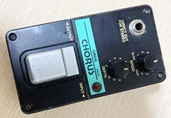 I put out the YAMAHA chorus "CH-01" that I bought when I was a student more than 30 years ago, which was sleeping in the drawer. This effect pedal could be incorporated into YAMAHA's "PSE" system board, and was an epoch-making effect pedal at that time. I bought it because I learned that it was used by Mr. Noro of Casiopea (Japanese fusion band) and I longed for it. When I was a student, I didn't have money and I couldn't buy a system board after all, and then eventually, I stopped using it.
Current conditions
This PSE series does not have an AC adapter terminal and is connected to the system board with a special wire. But a battery can be inserted, so I tried using battery power. After 30 years passed,its foot switch has brocken, but Its circuit board works perfectly!
When I tried it with my Stratocaster, it had a refreshing chorus sound, and it seems that it can still be used. Compared to the chorus of the ZOOM G3X multi-effects processor unit, the sound is chunky and has a good analog feel. There is almost no noise.
So I decided to disasemble this CH-01 and put it in a new aluminum enclosure to remake it.
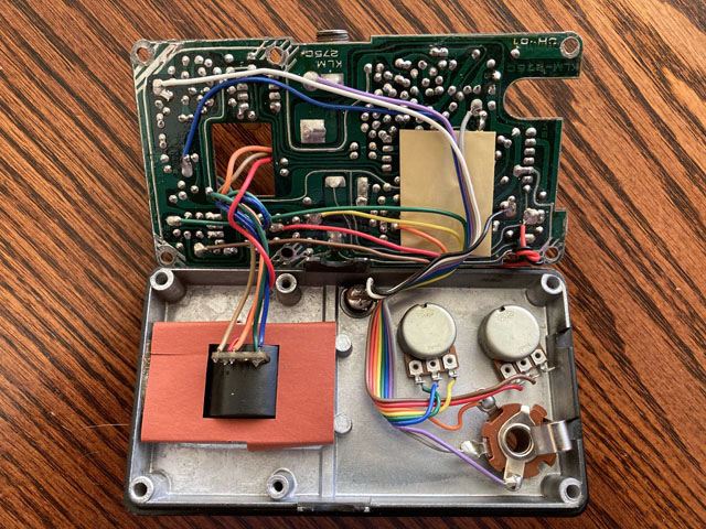
Disassemble the original CH-01
Circuit board survey
The YAMAHA CH-01 is so old that I can't find any schematic information on the internet. There is information that it is the same circuit as KORG's CHR-1, and I looked at the found circuit diagram of the CHR-1, but at first glance, the number of operational amplifiers and transistors is different, and it seems that that is not the same circuit. Therefore, I decided to remake it by looking at the actual wiring.
The structure of the YAMAHA CH-01 board is that the in / out phone jacks are directly attached to the board, but the potentiometers and switches are hand-wired using colored flat cables. This board design seems an old manufacturing method of the 80's.
The pods are a 500K C curve and a 100K B curve. These aren't broken, but I decided to replace them with new potentiometers. So, I found out where these pods were routed from the board.
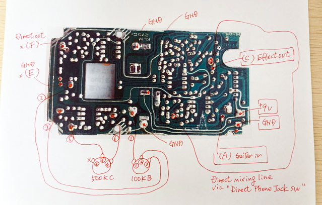
Print a photo of the board, check the original wiring condition and write
Parts used
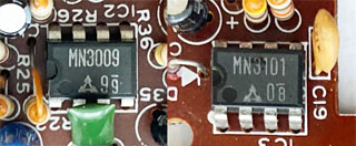 The characteristics of the sound of the analog chorus are due to the delay by BBD and the clock generator circuit. MN3009 and MN3101 are used for this. The MN3009 is a BBD with 256 stages of bucket elements, but it is no longer manufactured. In normal usage, the delay time is about 10ms. The slightly understated chorus sound probably comes from this short delay.
Watching the switch and jack wiring
The jacks are directly attached to the board. I decided to remove the jacks and replace them with new parts to put them in a new enclosure. The CH-01 has a direct out for stereo, but I have no plans to use the stereo out, so I removed this output.
The switch has two circuits, signal ON / OFF (switching between true bypass and effect out) and LED ON / OFF. These are manually wired to the board (marked with the ABCDE symbol) with cables. Input / output switching circuits and LED resistors are also mounted on the board.
This time, the switch is replaced with a new part, and the effect and LED ON / OFF are configured by the wiring of the switch terminal, so I decided to take out only the guitar input and the effect out from the circuit board.
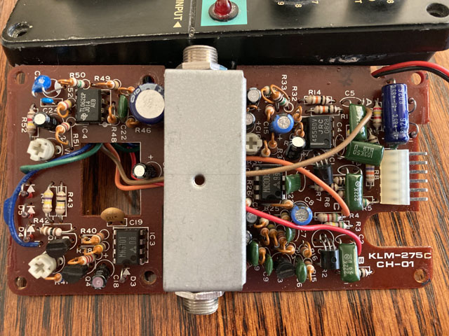
Jacks directly attached to the board
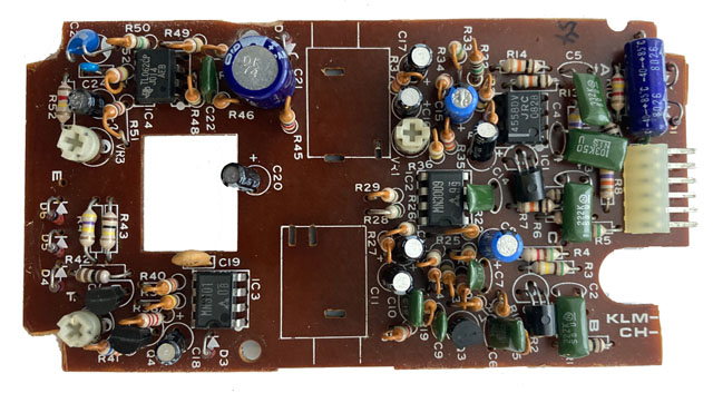
Board front side with wires removed from the original board
Circuit board size issue
I wanted to use the HAMMOND "1590N1" enclosure, but the short side of the CH-01 board is about 2mm larger than it fits in the enclosure. In addition, the corners of the screw part of the enclosure will also interfere. The only way to push it into the 1590N1 is sandpapering the board to make it smaller.
When observing the trace, I found that the circumference of the board is GND, and even if it is removed, there is no major problem in the circuit. Therefore, I cut both sides by 1 mm, cut out the corners, and forcibly processed it to a size that fits in the enclosure.
I made the board smaller by scraping it with coarse sandpaper. The corner was forcibly scooped out with a utility knife and nippers. Since the GND is broken at only one corner, I connected it with a wire.
Due to the large size of the board, no batteries can be inserted. Therefore, I will always connect the AC adapter and incorporate it into the effect pedal board.
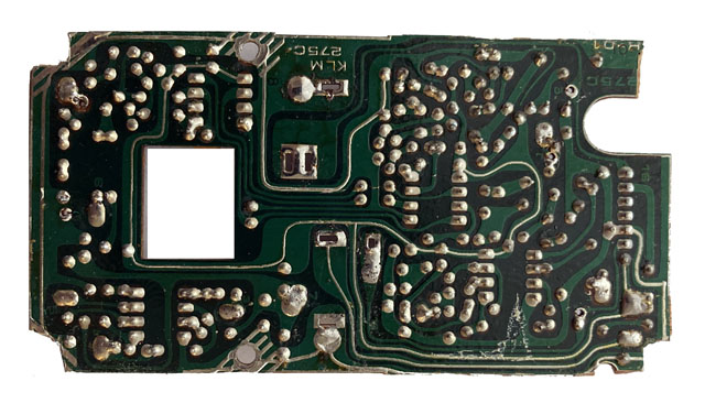
Board back side with wires removed from the original board
Enclosure processing
In CH-01, the jacks are directly attached to the board, and in order to avoid interference with the switch, there is a square hole in the board. The jacks and switche must be aligned with the board in order to fit into the enclosure. The potentiometers and AC adapter jack have been positioned so that they can be placed under the board.
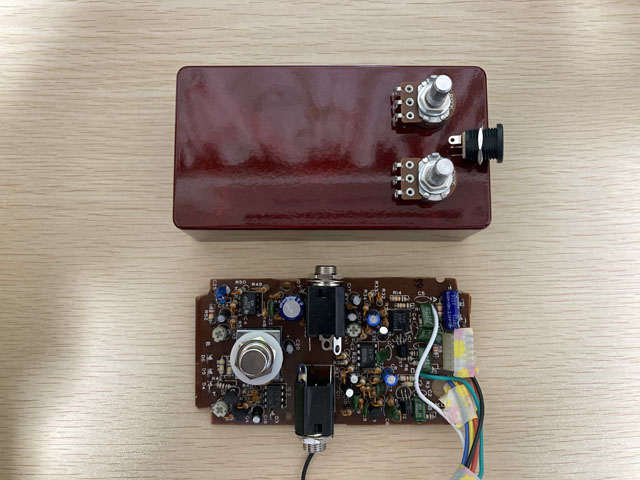
Considering placement position
As usual, after positioning the holes, first make holes with a 3mm drill and then widen the holes with a 6mm drill so that the holes position do not shift. In addition, use a reamer to widen the holes to fit the size of the potentiometers or jacks. For the LED, make a 3mm hole so that its head comes out, and fix it with instant glue from the back side.
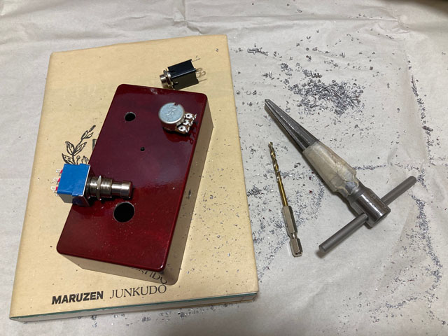
Drilling holes with a reamer
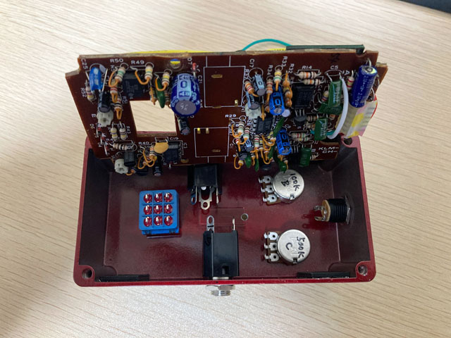
Before wiring inside, parts installation completed
Wiring in the enclosure
I wired to the new potentiometers, jacks, and a switch as I checked the wiring status of the original YAHAMA CH-01. This time, I wrote the wiring diagram on a printed photo of the board, so the actual wiring work was completed in no time. Probably less than an hour. I made the wire length as short as possible and also allowed the board to be turned inside out.
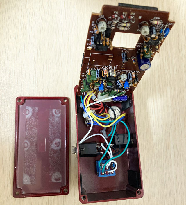
Internal wiring status
The YAMAHA chorus is back!
For this enclosure, I chose the dark red color called "Crimson Red" sold by Garrett Audio. The sound is, of course, the same as the original YAMAHA. The digital multi-effects processor are more flashy and more effective than this analog chorus, but its sound feels thinner. This analog chorus has a thick core sound. Whether it's a clean-tone chord backing or a low-gain overdrive solo, this analog chorus has a strong presence in the band. Maybe I'll use the multi-effects' chorus and this analog chorus for different purposes alternatibely.
I am very happy that this analog chorus has been revived. I'm glad I kept it for more than 30 years without throwing it away.
Sound sample
The same phrase will be played twice. The first half is OFF (buffered bypass) and the second half is ON.
Recording environment: Fender Stratocaster -> Self-made Centaur -> ZOOM G3X (Fender Twin Reverb clean simulation) -> UR22mkII -> DAW (Studio One)
![]() Sound sample(MP3)
Sound sample(MP3)
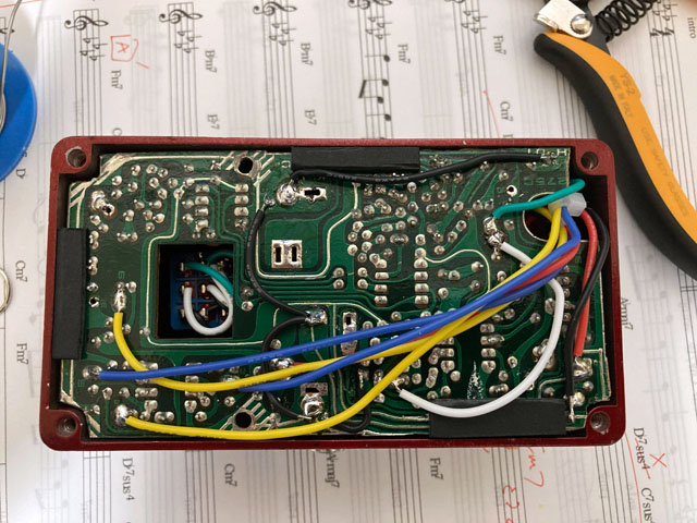
Before tightening the back cover
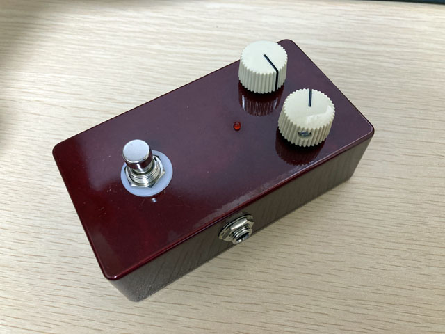
Completed! The color is Crimson Red!
I've created a page about the tools you need to make your own effects pedals and the basics of how to make them. Please refer to it.
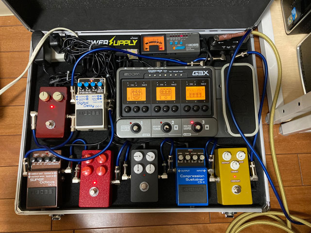
Built into my own effect pedal board
Click here to see my latest pedal board updated from the above photo.
Language
Self-made
effect pedals
- Pedals list page
 Tool selection
VEMURAM Jan Ray
Xotic BB preamp
Klon Centaur
 Revived old Chorus
 MXR Envelop Filter
 BBD Analg Delay DM-3
 600ms Analog Delay
 Arduino Analog Delay
 BBD Analg Chorus CE-3
CMOS Octaver OC-2
 Riot using chip parts
 Original design noise gate
 EP & MICRO AMP duo
 Keeley 4 Knob Comp
 MXR Phase 90 MOD
 Keeley Blend Comp
 DM-3 longer delay time
 ISP Decimator V2164


