MXR Phase 90 MOD: Classic Phaser Surface-mounted
Self-made Guitar Effect Pedals
Explore the articles to learn more about your favorite effect pedals.
|
Phaser, one of the classic effect pedal
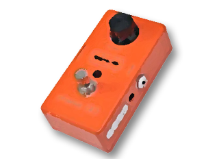 I think the phaser is one of the classic effects pedals. The operating principle consists of two notch filters, and the depth of this filter is variable by the triangular wave generated by the LFO. The result is a unique wave-like effect. This pedal is often used not only for guitars but also for Rhodes pianos. When I was in high school, I liked Richard Tee's Rhodes with Phase 90.
I've never used the MXR Phase 90 and have been using the BOSS PH-1R I bought 35 years ago. I think the sound output is almost the same as the MXR, but the PH-1R has a knob called RESONANCE that emphasizes the effect by giving feedback. I'm making a pedal board now. Since the PH-1R is large in size, I decided to make a mini-sized Phase 90 using surface-mounted chip components.
Slightly changed the circuit of Phase 90
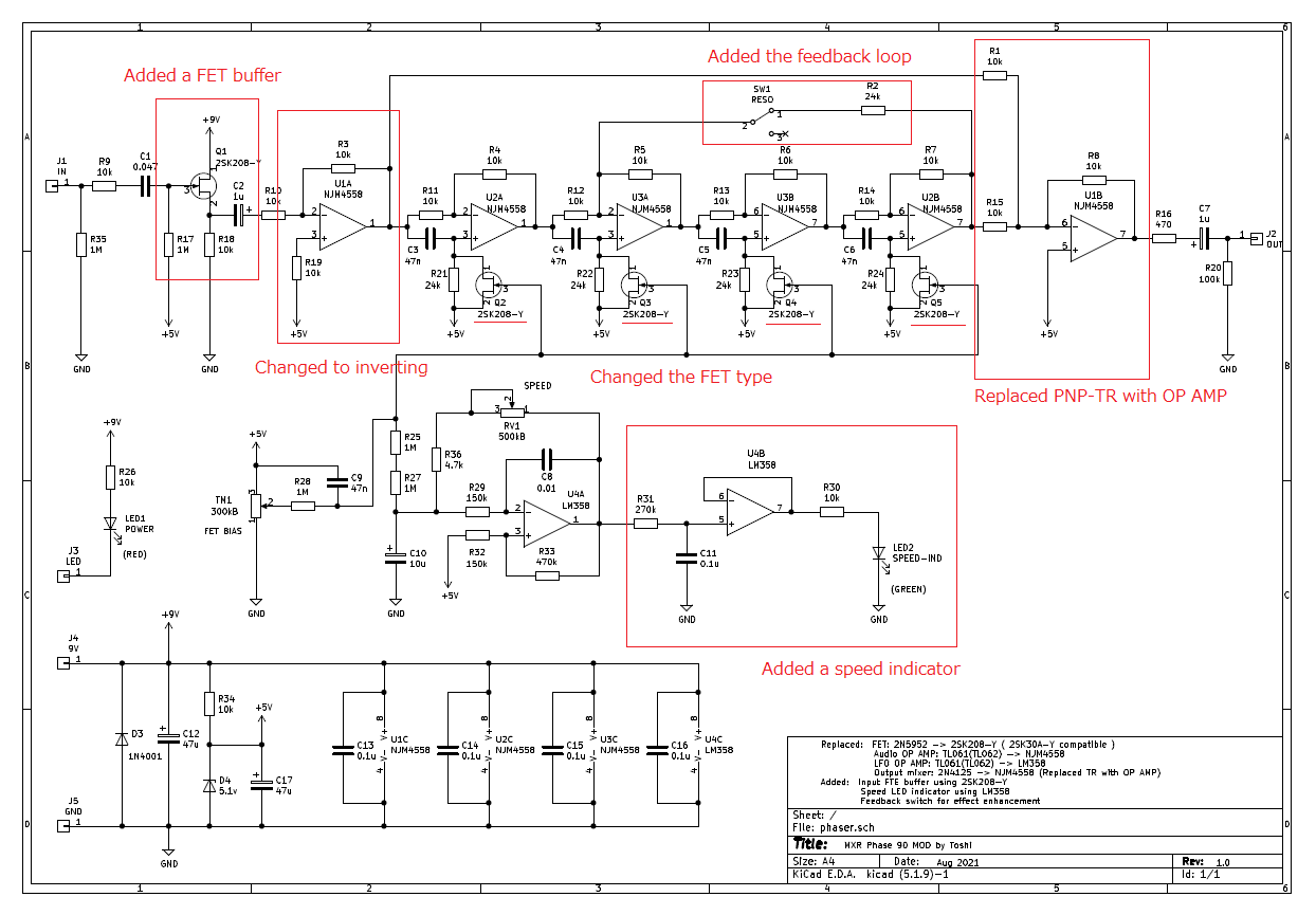
In the output stage, the original MXR has a mixer circuit with one PNP transistor. 2N4125 is used here, but since the surface mount component was not available, I changed it to an operational amplifier. An operational amplifier mixer usually consists of an inverting circuit in which the + terminal becomes virtual ground. This inverts the phase of the output, so I changed the operational amplifier in the input stage to an inverting circuit so that the phase returns to the original. However, in the case of an inverting circuit, since it is affected by the input impedance, a FET buffer is inserted before the input inverting operational amplifier.
Added speed indicator
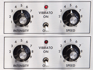 The Rhodes piano had a red lamp on to indicate the speed of the tremolo. When I was in high school, when I was watching a jazz concert, I was curious about this red glowing lamp on the Rhodes piano. So I decided to add an indicator to this phaser to show the speed.
The indicator can be realized by turning on the LED using the square wave output from the LFO. Since it is unpleasant to affect the original operation of the LFO, the rest of the dual operational amplifier is used as a buffer to reduce the load and turn on the LED. In addition, a time constant is added by CR so as not to generate edge noise of a square wave.
Purchase of surface mount components
Change to available surface mount components(SMD)
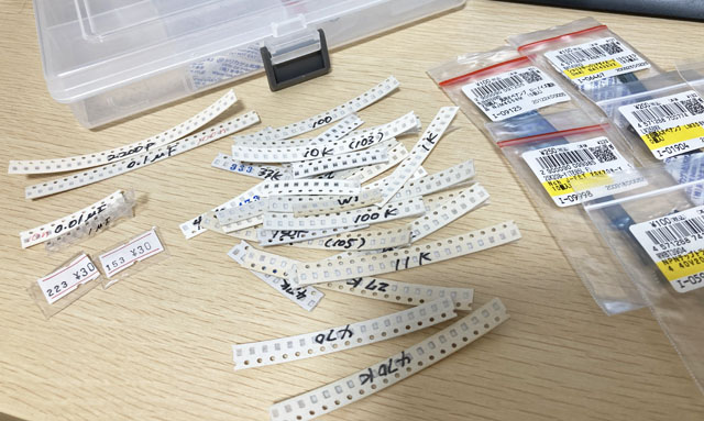
Most of the ICs and FETs used in the actual MXR are not available as surface mount components. A general-purpose operational amplifier TL062 is used, but I couldn't find the surface mount version, probably because it is a fairly old IC. Therefore, I changed to parts that can be easily obtained by mail order and purchased them.
FET: 2N5952-> 2SK208-Y (2SK30A compatible)
OP-AMP for audio: TL062-> NJM4558D
OP-AMP for LFO: TL062-> LM358 (for single power supply)
Create a PCB using surface mount components
33mmx38mm surface mount PCB
I made a 33mmx38mm surface-mounted printed circuit board to fit in a mini-sized enclosure. This is the 5th mini-sized effector made by myself. I can now make anything with "KiCAD design + Fusion PCB manufacturing". Small surface mount components (SMDs) are cheaper than large through-hole components (THDs), and many circuits can be mounted on a small board, so I don't feel like going back to through-hole component boards anymore.
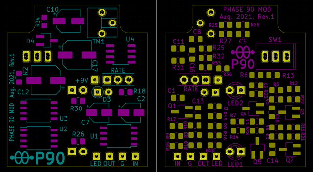
Parts pad and silk printing
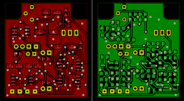
Trace
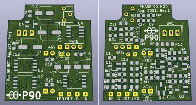
KiCAD 3D image
KiCad PCB design data
The PCB data created using "KiCad (Windows 64-bit) Version: (6.0.4), release build" is provided. The ZIP file contains the schematic, board design data, and original component data. Please read the terms of use and disclaimer in the attached "readme.pdf" before using this data.
Pots directly attached to the board and toggle switch
The original Phase 90 has only one speed-changing pot. This time, as a modification, a feedback resistance and its ON / OFF switch are added.
This pot and toggle switch are directly attached to the PCB. For the toggle switch, I made a hole for the terminal on the board and could attach it directly. However, pots that can be directly attached are not sold. Therefore, I am making my own pot using a universal board and an L-shaped pin header as shown in the picture below.
Design a board using KiCAD
The PCB was designed using the "KiCAD" that I was used to. I chose "2012" as the size of the surface mount part, and used a footprint of a large pad (the part where the part is soldered) so that it can be hand soldered.
Regarding the 8-pin operational amplifier, I used two types (NJM4558M and LM358MX) this time, but the size of the package is slightly different. It has a model number indicating the shape such as "SOP-8" and "DMP8". The corresponding parts are registered in the KiCAD library and must be selected correctly.
Also, the last time I used the chip transistor (Package SOT-23), the standard library pad was too small. Therefore, when hand soldering was performed, the solder did not flow well to the pad, causing poor soldering.
This time, instead of using the parts library (footprint) as it is, I am using it by modifying the registered parts, increasing the size of the pad by about 1.0 mm, and registering it in my own library.

Left: Footprint in the standard library
Right: Larger pad for hand soldering
In addition, it is necessary to pay attention to the positions of the pot and switch terminals to be directly attached. I decided the position of the pot terminal (L-shaped pin header) hole on the board based on the hole position to be drilled for enclosure. The PCB is just barely large enough to fit in the enclosure, so if this position is incorrect, it will not attach to the enclosure. Therefore, I measured the distance of the hole position with KiCAD and decided carefully. Similar attention should be paid to the hole positions of the two LEDs.
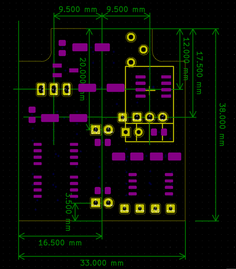
Order from Fusion PCB
As usual, I created Gerber data, packed it in a ZIP, and ordered it from the Fusion PCB site. The PCB arrived in about two weeks. FusionPCB has a longer delivery time than other PCB manufacturing services, but the quality of the PCB is high and stable. This time it took me two weeks because I chose a special blue resist color.
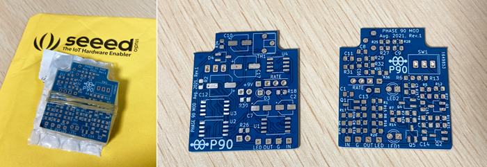
Hand soldering of parts
The surface mount parts are really small, and it is a soldering work using tweezers. I implemented it using the stand loupe I purchased earlier. It is necessary to check the constants one by one and then solder them by hand. If you make a mistake in the constant, it will be difficult to find the mistake later. The constants are printed on the resistors, but not on the capacitors. I carefully checked the constants when picking up the taped surface mount component.
Drilling and mounting the enclosure
This time, the pot and LED are directly attached to the board, so the hole position of the enclosure needs to be drilled with millimeter accuracy. I used KiCad to draw the relative position of each part on the PCB and copied it to the enclosure.
The procedure for drilling a hole at the correct position with an electric hand drill is as follows. Even if it is troublesome, it is better to do this to make a hole in the correct position.
1) First, use a sharp screwdriver to dent the center of the hole position.
2) Place the tip of the drill on the recessed hole position and make a hole with a 1.2 mm drill.
3) Next, widen the hole with a 3mm drill around this hole (LED ends here).
4) Further widen the hole with a 6 mm drill
5) With a taper reamer, widen the hole according to the hole diameter of each part.
One thing to keep in mind when drilling with a hand drill is not to push the tip of the drill during drilling. If you apply unnecessary force, a thin drill like 1.2mm will break easily. Also, in the case of a 6 mm thick drill, the groove of the drill will bite into the nclosure and rotate together with the nclosure. This is very dangerous.
Rather than pushing a drill to make a hole, I think it's more like shaving the nclosure lightly with the tip of the drill and gradually expanding the hole.
Placement within the enclosure
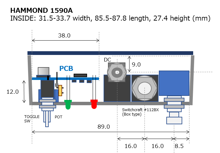
The layout image of the parts and boards in the enclosure is shown below.
Mounted pot and switch on PCB
The height of the board mounting inside the enclosure is determined by the height of the toggle switch. Therefore, solder the pot or LED in the following way.
1) First, solder the toggle switch to the PCB.
2) With the pot lead (processed L-shaped pin header) inserted into the hole in the board, attach the switch and pot to the enclosure. This will determine the height of the pot.
3) Solder the pot leads while still attached to the enclosure.
4) In the same way for the LED, attach the switch and pot to the enclosure with the LED lead inserted in the board, and after confirming that the LED head is correctly out of the enclosure, solder it as it is.
All parts including switches, pots and LEDs are integrated with the PCB
Operation check
Before incorporating it into the enclosure, I checked the operation with only the PCB. As usual, I generated a sine wave with free software on my PC and input the signal from the audio i / o (steinburg UR22mkII) to the PCB.
I inserted the signal input / output wires from the PCB into the breadboard, and then connected the batteries.
Luckily this time it worked without any errors. The LFO worked fine, and the blinking LED of the speed indicator I added worked just as I had imagined.
FET bias adjustment
The FET attached to the notch filter normally requires matching (measures LDSS and selects FETs with similar values), but it was difficult to measure because it is a surface mount component. Therefore, I do not match FETs. Also, in order to obtain a clean phaser effect, it is necessary to adjust with the drive bias of the FET (using semi-fixed on the PCB).
This adjustment is critical and difficult, but if you apply too much bias, the FET will turn on for a long time, and if the bias is small, the FET will turn off for a long time. This adjustment was decided by searching for a good feeling while listening.
Regarding FET matching, I'm not sure if it matches or not, but I think it's okay because it sounds properly.
Sound samples
The resonance switch is OFF. A thin reverb is applied in the DAW.
![]() Sample: Chord phrase (MP3)
Sample: Chord phrase (MP3)
![]() Sample: Rhythm slightly overdrived (MP3)
Sample: Rhythm slightly overdrived (MP3)
The recording environment is:
Guitar (Stratocaster, single front pickup) -> Self-made phaser -> MOOER Preamp006 (Fender blues deluxe clean simulator, cabinet ON) -> UR22mkII -> DAW (Studio One)
Completed by incorporating into the enclosure
Create an original sticker
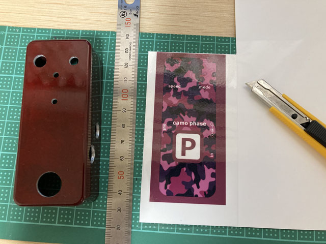
This time I used a red painted enclosure. I wanted to make it look like a commercial product, so I put a sticker on the top of the enclosure. I printed a design image made with PowerPoint on sticker paper with an inkjet printer and cut it out. Holes such as pots are cut out according to the holes after sticking a sticker.
I didn't name it "Phase 90". I want to emphasize the originality that changed the circuit. I named it "camo phase" with a camouflage pattern as a motif.
A nice mini "camo phase" is completed!
The sticker on the eclosure looks good. Like the tremolo indicator on a Rhodes piano, the green speed indicator lights up fluffy and is awesome!
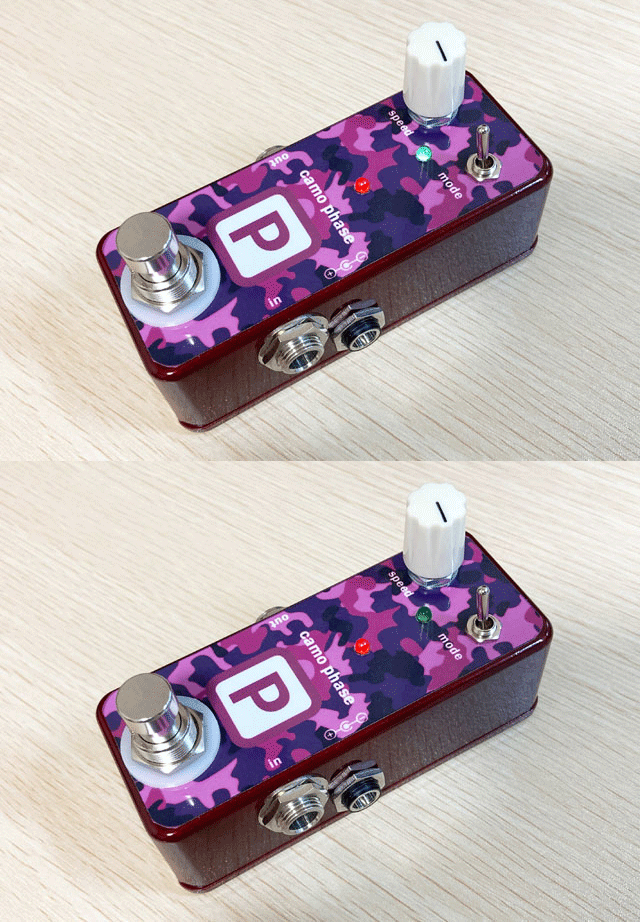
(Blinks as above. Animated GIF. Not an actual video.)
I would like to add a loop switcher to the pedalboard that I am remaking.
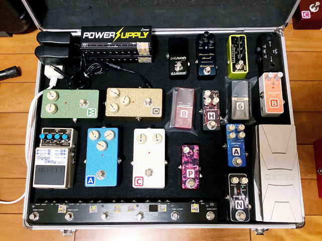
Pedalboard whose placement is being devised
Click here for the latest pedal board updated from the photo above.
Language
Self-made
effect pedals
- Pedals list page
 Tool selection
VEMURAM Jan Ray
Xotic BB preamp
Klon Centaur
 Revived old Chorus
 MXR Envelop Filter
 BBD Analg Delay DM-3
 600ms Analog Delay
 Arduino Analog Delay
 BBD Analg Chorus CE-3
CMOS Octaver OC-2
 Riot using chip parts
 Original design noise gate
 EP & MICRO AMP duo
 Keeley 4 Knob Comp
 MXR Phase 90 MOD
 Keeley Blend Comp
 DM-3 longer delay time
 ISP Decimator V2164


