Self-made overdrive pedal VEMURAM Jan Ray clone
Self-made Guitar Effect Pedals
Explore the articles to learn more about your favorite effect pedals.
|
Gorgeous overdrive Jan Ray
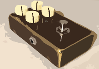 The Jan Ray is an overdrive pedal made by the Japanese company VEMURAM. It offers a clean boost to low-gain distortion, which beautifully highlights the core sound of the guitar strings.
The genuine Jan Ray comes in a luxurious brass enclosure and is considered one of the top-tier effect pedals. Because of this, it costs over $350. Wow!
So, I decided to build my own using the circuit diagram and board layout I found online. This page documents my journey from start to finish in creating my own Jan Ray pedal.
About circuit
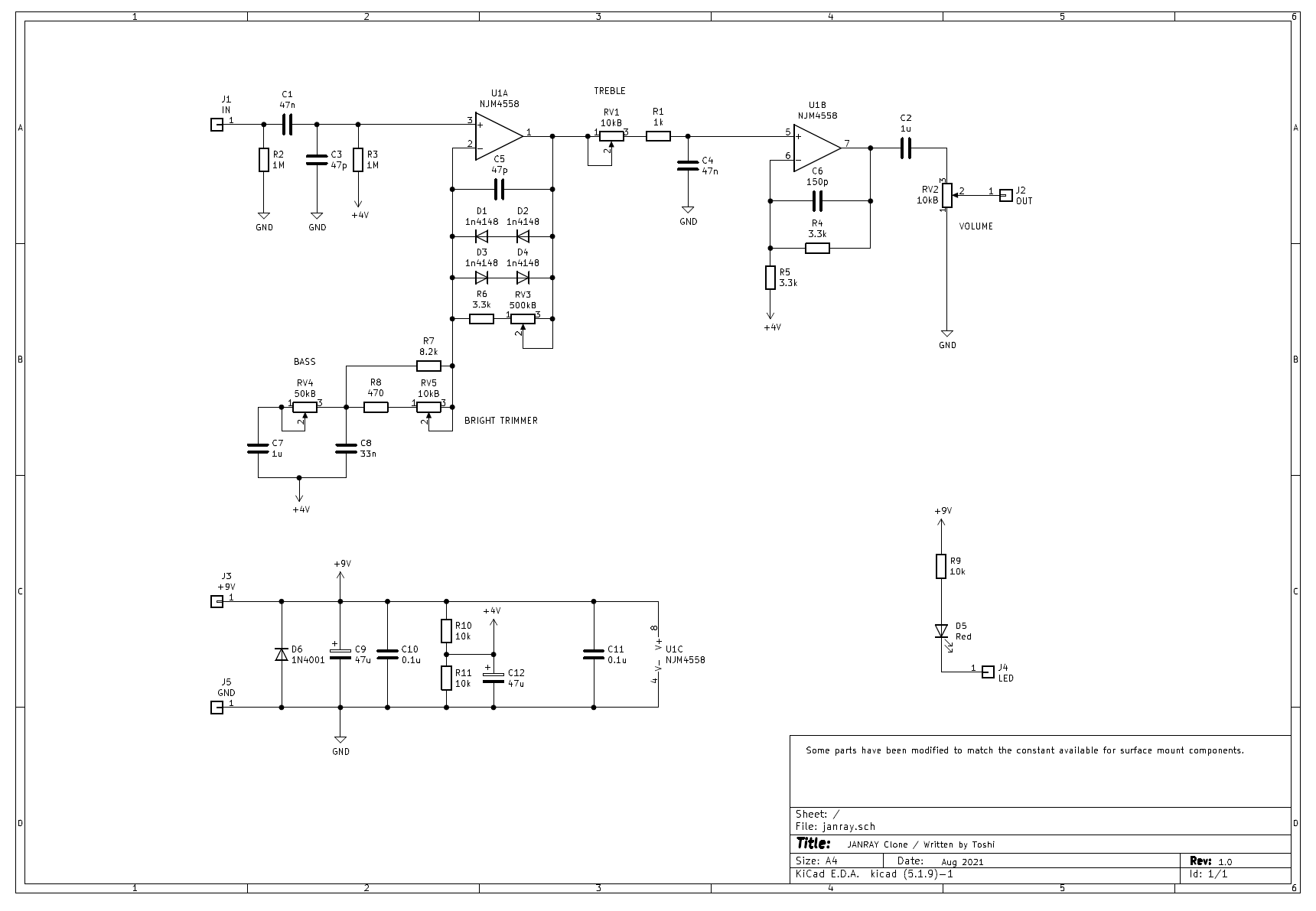
It appears that the real Jan Ray's circuit boards and parts are painted black or glued together, making it difficult to identify the specific components and circuits used. However, an engineer disassembled a purchased Jan Ray, removed the trace mask, detached the parts, measured the resistance values and capacitor capacitance, and documented it all on a circuit diagram. Impressive work!
In terms of the circuit design, a double diode (1N4148, a standard switching diode) is placed in the feedback loop of an operational amplifier to create distortion. It shares the same circuit as the existing "Timmy" effect pedal, but with slight differences in resistance values, diode wiring, and capacitor capacity. Essentially, it's a Timmy clone. If you're not into DIY and don't mind these subtle sound differences, you might be better off buying a Timmy.
However, the Jan Ray's enclosure is made of brass, and the components used are likely of higher quality. Given that professionals highly rate the Jan Ray, there's no doubt that there are some differences compared to the Timmy. If you want the authentic experience, you should buy a Jan Ray. There are many comparison videos of the two on YouTube, so you can listen and compare for yourself.
PCB supplier
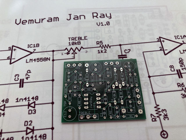
When I made my own Centaur pedal last time, I used point-to-point wiring on a universal board based on a circuit diagram I found online. I enjoyed this method, and it was one of the pleasures of the project. However, my aging eyes have made detailed work more challenging, so this time I decided to use a printed circuit board (PCB) purchased online. As a result, it was much easier and worked perfectly on the first attempt.
For the components, I bought everything (parts, switches, jacks, solder, potentiometers, knobs, painted enclosure, etc.) from the Japanese mail-order effect pedal parts shop "Garrett Audio." Excluding the PCB, the total cost was about $45.
About parts and enclosure
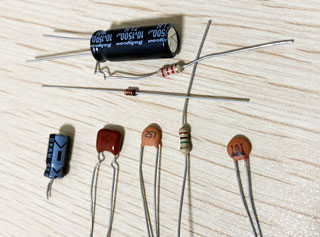
I bought cost-effective, general-purpose electronic components. The resistors are carbon 5%, 1/4W, and the capacitors are the cheapest available, regardless of type. The operational amplifier is a JRC4558DD (low noise type). Since the sound can change depending on the operational amplifier, I used a socket so it can be easily swapped with another one.
 My Opinion:
Especially with distortion effect pedals, they are not HiFi audio devices, so it's meaningless to use high-end audio parts. Changing the type of parts can alter the sound, but using higher-end parts does not always result in better sound.
Even if I thought it sounded good one day, I might not feel the same way the next day because my mood could change. I remember experiencing this when I was cloning the Centaur. It's true that after listening for 5 or 10 minutes, your ears get accustomed to the sound, making it hard to judge whether it is good or bad.
There is no such thing as "absolute" or "best" in sound. It depends on our mood at the time. Therefore, it doesn't make sense to focus on the type of parts, so I just use economical ones.
Enclosure processing
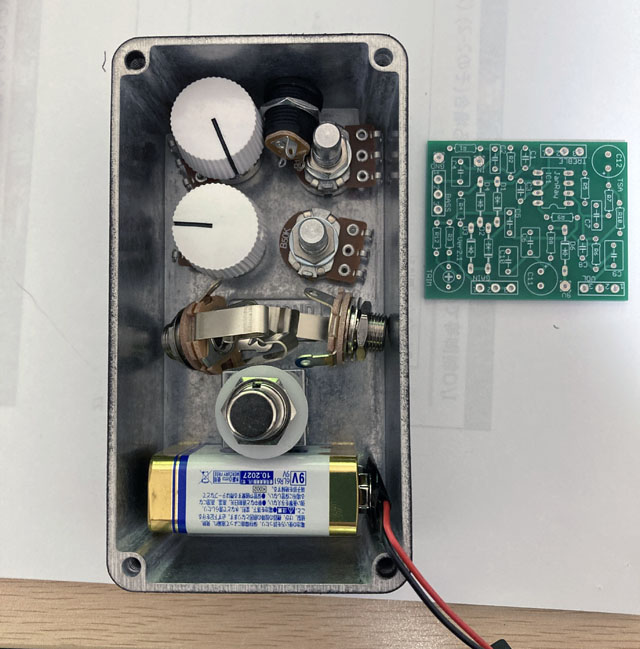
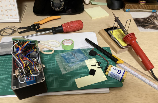
I chose a HAMMOND 1590BS enclosure with a rough black paint finish. It cost $15. Since the effect pedal needs to house a battery, pots, a footswitch, and phone jacks in a small box, the hole positions must be carefully determined to avoid interference. I arranged the actual parts in the enclosure and decided on the approximate positions.
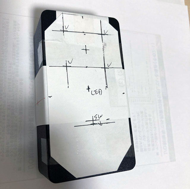
First, write down the position on a piece of paper, tape it securely, and use a sharp screwdriver or ideally a center punch to mark the center of the hole. Next, drill a small hole using a 3mm drill bit at the marked point, then widen the hole with a 6mm drill bit to accommodate a reamer.
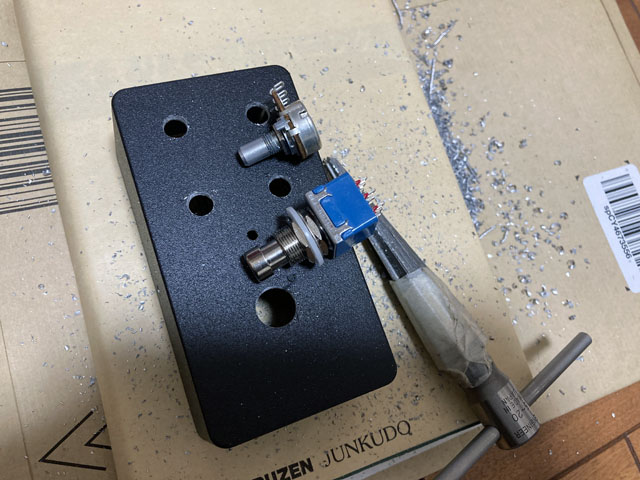
Since the holes for potentiometers, jacks, and switches vary in size, decide on the exact size by fitting the actual parts and gradually widening the holes with a reamer.
Wiring in the enclosure
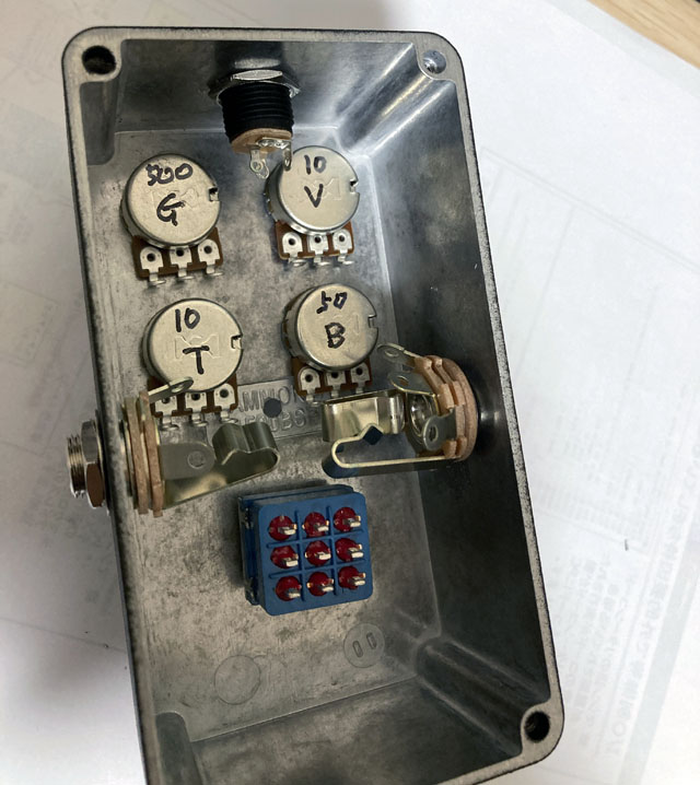
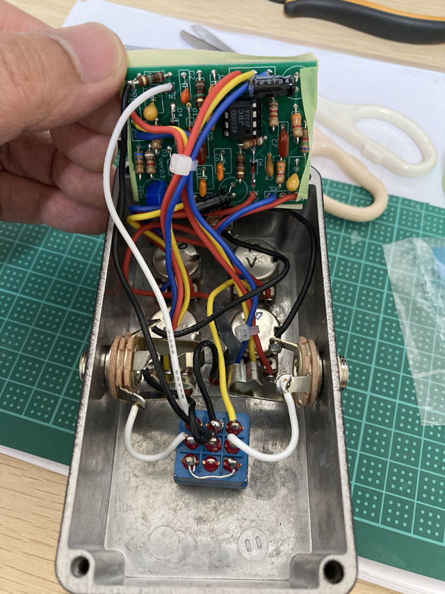
Once the potentiometers, jacks, and foot switch are attached to the enclosure, begin wiring the interior. I used 24 AWG flexible wire for the wiring. There are two types of electrical wires: "flexible wire," which is a bundle of thin wires that I used, and "solid wire," which is a single solid wire. Solid wire holds its shape well, resulting in a neat appearance. However, it can break easily if bent repeatedly, so it may not be ideal for beginners. Beginners should opt for "flexible wire."
The LED fits snugly into a 3mm drill hole. After inserting the red LED, secure it with instant adhesive applied from the back side. The wiring between the potentiometers (pods) and the PCB should be kept as short as possible to minimize noise. However, it's convenient to leave enough length to easily turn the board over for troubleshooting.
Output sound check
This time, using a PCB ensured there were no wiring mistakes, so I checked the sound output after everything was attached to the enclosure. I discovered that the GAIN potentiometers No. 1 and No. 3 were wired in reverse, causing the GAIN knob to function in reverse. However, the other components worked flawlessly.
When I previously attempted to build my own Centaur on a universal board, it didn't work correctly on the first try. This time, using a PCB made the process super easy!
Based on many YouTube reviews, backing chords played with a Stratocaster's single-coil pickup sound excellent with the Jan Ray. For rhythm guitar, using a low-gain overdrive like the Jan Ray slightly distorts the peaks and compresses them, which is preferable to a clean tone or a compressed sound like the DynaComp.
With a Les Paul equipped with humbuckers, raising the GAIN and setting the Les Paul's volume to around 6 approximates the original distortion of a Fender amp. Increasing the volume to MAX comfortably pushes it into overdrive. I find that the guitar's volume knob responds quite well in adjusting the tone.
Sound samples
I'll play the same phrase twice. The first half will be with the pedal OFF (buffered bypass), and the second half will be with the pedal ON.
Recording setup: Fender Stratocaster -> Self-made Centaur -> Mooer Preamp 060 (Fender Clean, Cabinet ON) -> UR22mkII -> DAW (Studio One)
![]() Chord backing(MP3)
Chord backing(MP3)
![]() Rhythm guitar(MP3)
Rhythm guitar(MP3)
It's done!
I closed the enclosure and completed my project. Unlike the real Jan Ray, which doesn't have printed labels on the knobs, I labeled mine with initial stickers on each knob. My custom black Jan Ray is finished, and I'm incredibly satisfied!
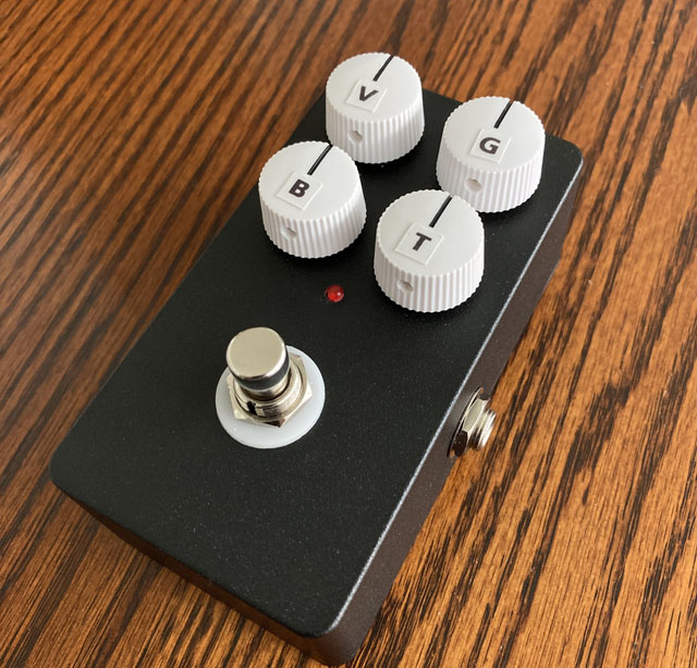
My own black Jan Ray clone completed!
[Addition] Miniaturizing Jan Ray with Surface-Mounted Chip Parts
It has been eight months since I completed the black Jan Ray clone mentioned in the previous article at the end of 2020. As indicated in the article index, I have crafted various effect pedals including distortion, auto wah, chorus, analog delay, octaver, compressor, phaser, and others. Recently, my focus has shifted to miniaturizing pedals using surface mount parts.
Pedal switchers and self-made effect pedals are integrated into my pedal board. Standard-sized pedals are too large for the board, prompting me to miniaturize wherever feasible.
As part of this effort, I created a surface-mount version of the bright red BB-PREAMP described earlier. The circuit remains identical, though I adjusted non-surface mount components to close alternatives.
Printed board design
When I made the black Jan Ray mentioned earlier, I used printed boards purchased online. To miniaturize pedals, I design and order all PCBs myself using the free software "KiCAD" and the Chinese board manufacturer "Fusion PCB". For sizes up to 10cmx10cm, 10 PCBs cost only $5. With DHL shipping adding $15, the total comes to around $20, which is incredibly affordable.
The PCB structure is double-sided through-hole, but since Jan Ray has a small number of parts, I could design it with components mounted on just one side. The left figure shows silk printing on the front side with component pads (where solder is applied), while the right figure displays the traces (red for the front side, green for the back side). In reality, both sides are filled with ground to ensure solid grounding, although this is hidden in the image below.
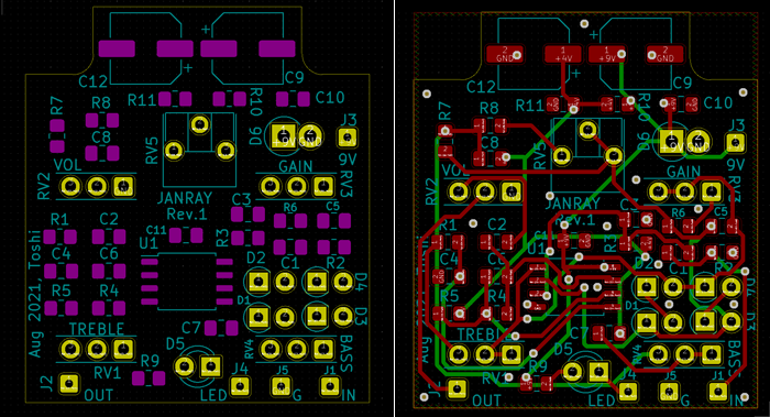
The following is a completed image of KiCAD's 3D display function.
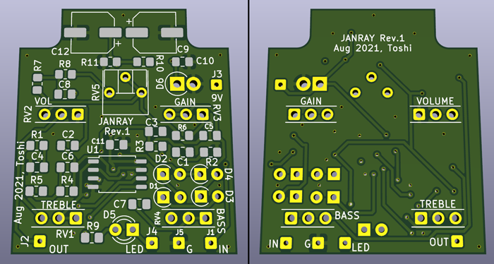
Completed Board Example
Here is the actual completed board. The delivery time can vary based on the resistor color specified during ordering. This time, I specified "black." The board arrived within 9 days (4 days for manufacturing and 5 days for DHL delivery) after placing the order on the website.
Please refer to the following page for details on PCB design.
PCB design using normal through hole components (Analog delay)
PCB design using surface mount components (Riot, Hi gain distortion)
KiCad PCB design files
I've prepared the PCB data using "KiCad (Windows 64-bit) Version: (6.0.4), release build." The ZIP file includes the schematic, board design data, and original component information. Please review the terms of use and disclaimer provided in the attached "readme.pdf" before utilizing this data.
Purchasing Surface Mount Components Online
I've created numerous effects pedals using surface mount chip parts. Details of the parts I purchased online are listed on the following page.
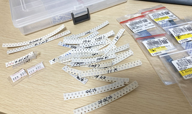
Mounting surface mount components
I use 2012 size (2.0mmx1.2mm) for chip resistors and chip capacitors when hand-soldering components. This size is just right for manual soldering work.
Electrolytic capacitors also use a surface mount type without lead holes. I don't believe changing resistors and capacitors to surface mount components affects the sound quality. However, for distortion-creating diodes, I use the same through-hole components as in the black Jan Ray to maintain the original sound.
Mounting involves picking up and soldering parts with tweezers. Due to their small size and the challenges posed by my aging eyes, I use a stand loupe (magnifying mirror) for assistance. Resistors, electrolytics, and ICs have constants and model numbers printed on them, but capacitors do not. Therefore, it's essential to carefully manage capacitor parts by noting their constants on the packaging tape.
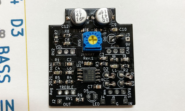
Refer to the Self-made Riot article for the hand soldering of surface mout components
Operation check
I'm currently using a small digital oscilloscope that I purchased for $40. To verify the potentiometer's rotation direction and gain settings, I output a test signal, such as a sine wave generated by free PC software, through the audio interface (Steinberg UR22mkII) and input it into the produced PCB.
I test the circuit board before integrating it into the enclosure. Currently, I insert wires from the PCB into a breadboard and connect them to the input/output jacks and power supply (9V battery).
This time, the sound was output correctly on the first try without any errors. There's a semi-fixed potentiometer on the board that adjusts the brightness of high frequencies. I'll fine-tune its position while listening to the output next.
Surface mount mini size Jan Ray sound sample
This is an interlude from the original song "Thinking About You," featuring my own Jan Ray pedal (surface mount version). The sound showcases lightly distorted, mellow tones using the front pickup of a Les Paul guitar.
Recording environment: Gibson Les Paul (front, tone 5) -> Self-made EP Booster -> Self-made ISP noise reduction -> This unit (mini size Jan Ray) -> MOOER MicroPreamp 006 (Fender amplifier cabinet simulator) -> UR22mkII -> DAW (Studio One)
![]() Thinking About You Interlude Solo (MP3)
Thinking About You Interlude Solo (MP3)
[Addition] Completed by incorporating into a mini size enclosure
Create an original sticker
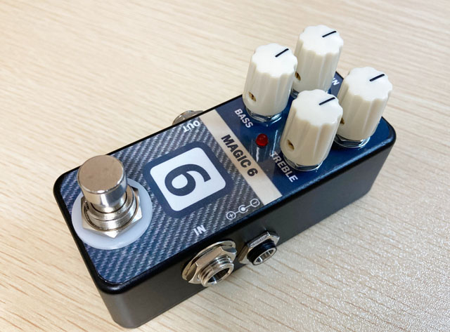
I housed the mini size Jan Ray in a "HAMMOND 1590A" enclosure. To add a personal touch, I created an original label using a sticker made with an inkjet printer and affixed it to the enclosure. The design is inspired by Fender's 1960s black face amplifier, aiming to replicate the distortion achieved with the "MAGIC6" setting (Volume 6, Treble 6, Middle 3, Bass 2).
Instead of "Jan Ray," I named this mini effect pedal "MAGIC 6" and incorporated the amplifier motif into the sticker design.
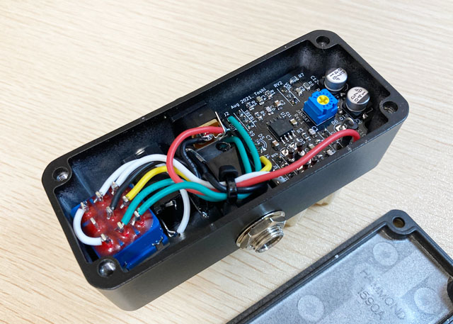
[Additional MOD] Modification to lower the output impedance
The "MAGIC 6" pedal features a VOLUME pot with a 10kΩ resistance directly connected to the output jack. Consequently, the output impedance varies, reaching a maximum of 10kΩ depending on the potentiometer's position. This higher output impedance could potentially affect subsequent pedals connected in the signal chain.
Furthermore, due to the lack of protection resistance at the output, there is a risk of overloading the operational amplifier if the output is shorted when the VOLUME is turned up fully.
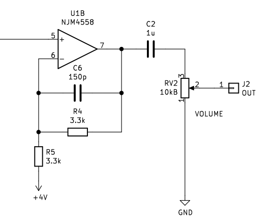
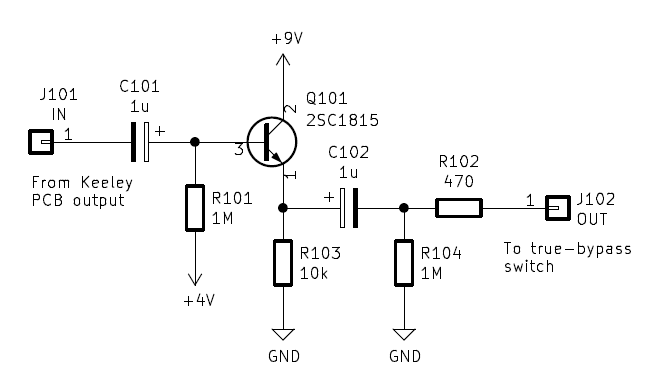
To address potential issues with output impedance, I modified my "MAGIC 6" pedal by adding a buffer circuit at the output. This modification lowers the output impedance to a constant 470Ω, similar to the approach used in the DIY modification of the "Keeley 4 Knobs Compressor."
The added circuit is a straightforward emitter follower using the NPN transistor "2SC1815." It was incorporated after the original PCB circuit without altering its design.
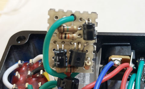
Created with a small universal board to fit in the enclosure
I used a small universal board to fit the "MAGIC 6" into its mini-size enclosure. Given the compact dimensions, I designed the board to fit snugly above the output jack, optimizing space inside the pedal.
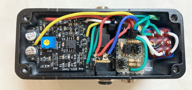
Achieves stable low gain overdrive
The addition of this circuit ensures stable tone and volume consistency regardless of how the switcher connections change with MAGIC6 ON/OFF.
I've found no sound difference between the JanRay clone made with through-hole parts previously and the current one with surface mount components. Unlike power amplifiers that require high current, effect pedals operate with low current, minimizing sound changes due to parts types. This reaffirmed that circuit configuration plays a decisive role in sound quality.
Here's my current pedal board setup, featuring numerous pedals managed efficiently with a switcher. I use the "One Control Agamidae Tail Loop," which accommodates 6 loops and has been modified with LEDs for effect loop status indication.
Check out the latest update incorporating the mini size JanRay (MAGIC 6) on my updated effector board here.
For beginners, I've created a resource page for selecting tools for DIY projects.
* The text on this page has been revised based on suggestions from ChatGPT.
Language
Self-made
effect pedals
- Pedals list page
 Tool selection
VEMURAM Jan Ray
Xotic BB preamp
Klon Centaur
 Revived old Chorus
 MXR Envelop Filter
 BBD Analg Delay DM-3
 600ms Analog Delay
 Arduino Analog Delay
 BBD Analg Chorus CE-3
CMOS Octaver OC-2
 Riot using chip parts
 Original design noise gate
 EP & MICRO AMP duo
 Keeley 4 Knob Comp
 MXR Phase 90 MOD
 Keeley Blend Comp
 DM-3 longer delay time
 ISP Decimator V2164


