EP BOOSTER & MICRO AMP using surface mount parts self-made report
Self-made Guitar Effect Pedals
Explore the articles to learn more about your favorite effect pedals.
|
Make my own buffer amplifier always used for input
When receiving a high impedance guitar output on the pedal board, the sound inside the board will be stable if the buffer is inserted first. It's understandable that many professional guitarists use "VITALIZER" as an input.
I set the GAIN of my own Centaur to zero and used it as an input buffer at all times. However, its size is large so I decided to make a buffer amplifier with a mini-sized enclosure.
I have already made Riot and pedals of the original noise gate with surface mount parts and put them in a mini size enclosure (HAMMOND 1590A), so I made a PCB of the same size this time as well.
Switchable between MICRO AMP and EP BOOSTER
Since the circuit of the buffer is simple, even a small PCB of 33 mm x 38 mm will have a considerable area left if surface mount components are attached to both sides. So, I decided to pack the old "MXR MICRO AMP" and the recently popular "Xotic EP BOOSTER" into the same pedal.
By the way, I also added the output to TUNER. This is a super simple buffer using just one transistor (used as an emitter follower).
My idea memo
Features of both circuits
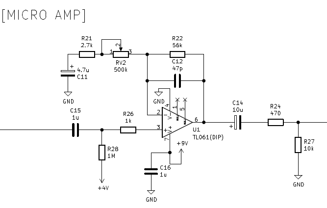
The circuit of MICRO AMP is an amplifier circuit of an ordinary non-inverting operational amplifier. There is no LPF that cuts treble on both the input and output, and it is a circuit that boosts with flat characteristics. Calculated from the constants used, pot adjustments can boost + 1dB to + 26dB.
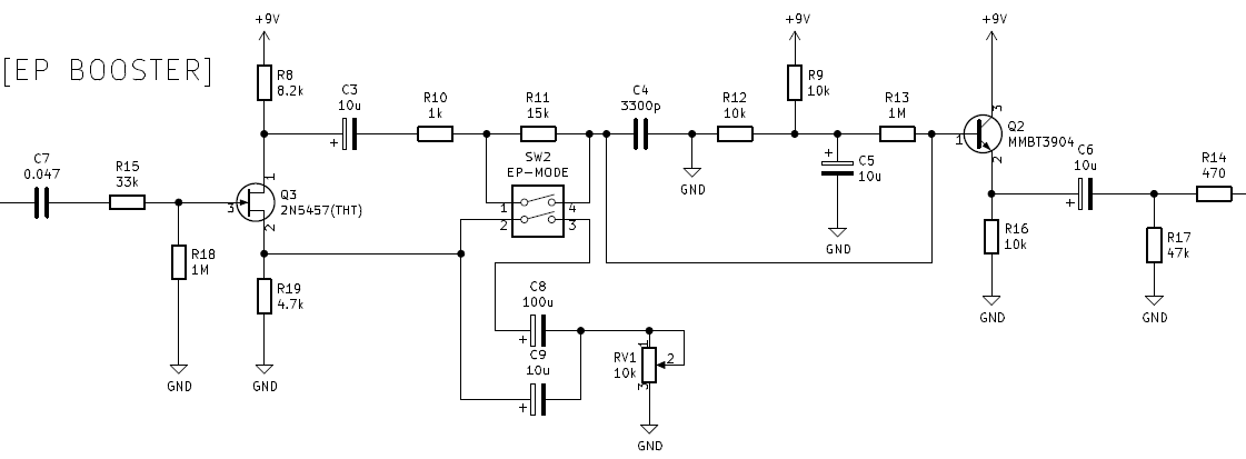
On the other hand, EP BOOSTER is a unique circuit that uses one FET and one transistor, and contains a CR filter that changes the frequency characteristics. This circuit seems to be based on the circuit of the tape echo preamplifier called Echoplex, and it seems to have the effect of pushing the low mid of the sound of the guitar. By switching them, the original sound of the guitar can be used for different characters.
Create a PCB using surface mount components
Designed with KiCAD
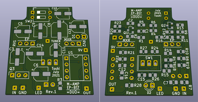
The printed circuit board was designed using the freeware KiCAD and ordered from "Fusion PCB" in Shenzhen, China. This is my 6th work. I made it using "2012" size parts and specified a large pad (the part where the lead of the chip part is soldered) so that hand soldering is possible.
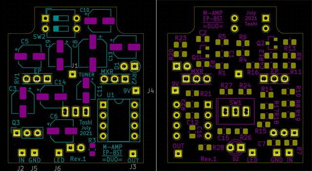
The method of arranging the parts is as follows:
After deciding the position of pots and a toggle switch, place the tall electrolytic capacitors, a DIP-IC, and lead parts (TFT, diode). On the back side, place the chip resistors and chip capacitors that the parts do not overlap with each other, all you have to do is connect them. Once everything is connected, fill the remaining front and back areas with ground (solid earth).
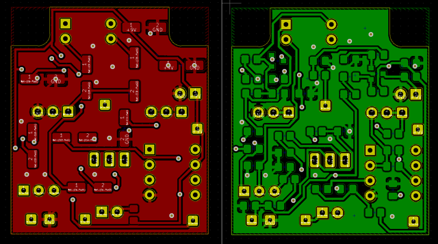
The KiCAD standard library does not have a toggle switch footprint (part hole position, solder pad shape data, silk printing), so I measured the parts I actually purchased and made them myself.
Particular attention was paid to the hole position of the toggle switch and the pots. Since the toggle switch is mounted directly, the center position of the part matches the hole position of the enclosure. However, because the pot uses a universal board to extend the leads (discussed below), the holes in the enclosure and the holes in the leads on the PCB are out of alignment. I calculated carefully and determined the lead position of the board. This position calculation was done using the CAD function of KiCAD.
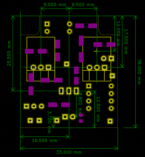
Another point to note is the direction of rotation of the pot. For frexible wire connection, you can correct the direction of rotation by connecting pins 1 and 3 in reverse. However, this time, the lead of the pot is directly attached to the board, so if the direction of rotation is wrong, it cannot be corrected. I've seen many times that turning it to the right increases the gain.
I also paid attention to the orientation of the toggle switch. I checked many times to see if the pot in the direction in which the toggle switch was pushed down would be effective.
KiCad PCB design data
The PCB data created using "KiCad (Windows 64-bit) Version: (6.0.4), release build" is provided. The ZIP file contains the schematic, board design data, and original component data. Please read the terms of use and disclaimer in the attached "readme.pdf" before using this data.
Order from Fusion PCB
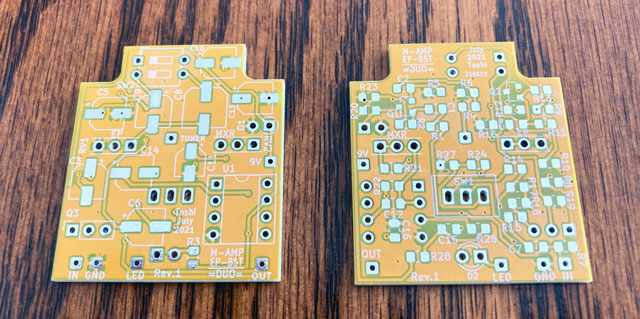
As usual, I created Gerber data, packed it in a ZIP, and placed an order from the Fusion PCB site. This time, I chose a "yellow" resist color that I haven't made yet. The cost is the same, but the delivery time is longer than the shortest "green".
About two weeks later, I received the board I ordered. The part number may be a little hard to see because the silk color printed on the yellow resist is white. However, I am satisfied with the unique board.
Mount components on the board
Purchase of chip parts
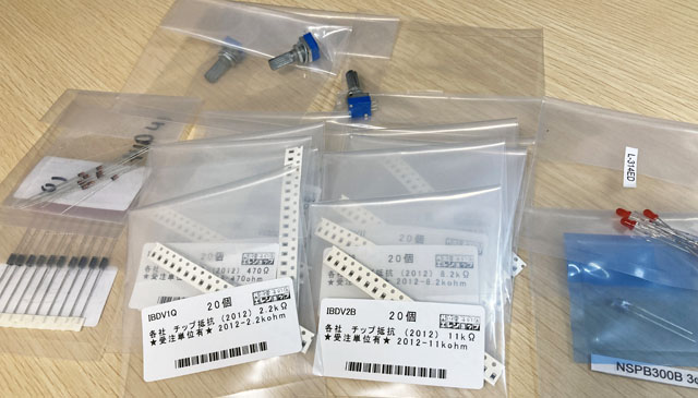
Since this is the third time to make a surface-mounted board, I used the rest of the chip resistors and capacitors. I bought all the semiconductors, but only the missing constants for the resistors and capacitors. Please refer to the Riot production page for how to purchase.
Soldering chip parts
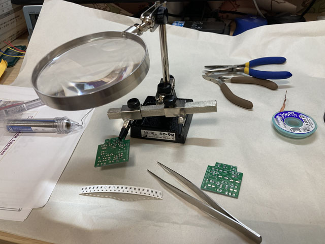
The surface mount parts are really small, and it is a soldering work using tweezers. I soldered it using the stand loupe I bought when I made the noise gate last time.
Regarding the TL061 (single operational amplifier) used in MICRO AMP, the surface mount version of the IC was not available at the mail-order parts shop that I always use. An alternative chip IC can be used, but I used the DIP type TL061 so that the sound did not change.
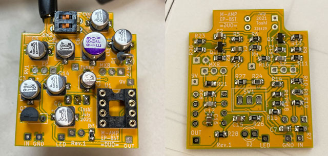
Also, the 2N5457 (FET) used in EP BOOSTER was not available as a chip component, so I used a normal leaded component. All others are surface mount components.
Attach the pot and toggle switch directly to the board
This time, for the first time, I tried to attach the toggle switch and pot directly. Most pedals sold by manufacturers have pots, switches, jacks, LEDs, etc. mounted on the board and are designed so that there are no wires to connect.
At this time, it is necessary to pay attention to the height of the parts. In order to mount the pot and switch on one board, the height to the enclosure hole must be the same. If I were a commercial manufacturer, I think I could make custom height-specified parts, but that's not possible.
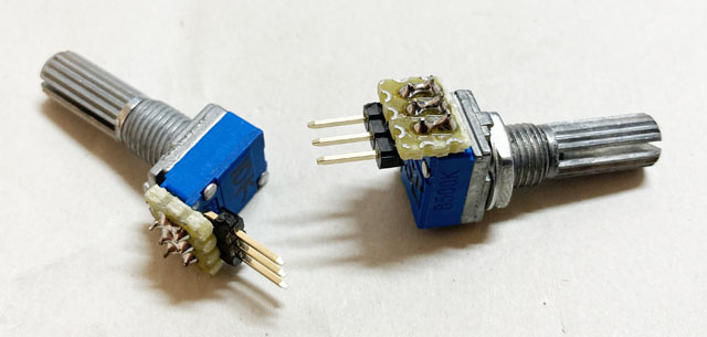
Therefore, based on the height of the toggle switch, we devised the lead of the pot so that the height can be the same.
The pot and L-shaped pin header are connected by a universal board, and the long pin header increases the length of the leads and allows for adjustable height.
This booster is always on, so there is no foot switch. A tuner out is attached to the switch space using a 3.5mm mini jack.
Drilling holes in enclosure
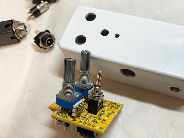
This time, the pot, toggle switch, and LED are directly attached to the board, so the hole position of the enclosure must be drilled with millimeter accuracy. I used KiCad to draw the relative position of each part on the board and used it to determine the hole position of the enclosure.
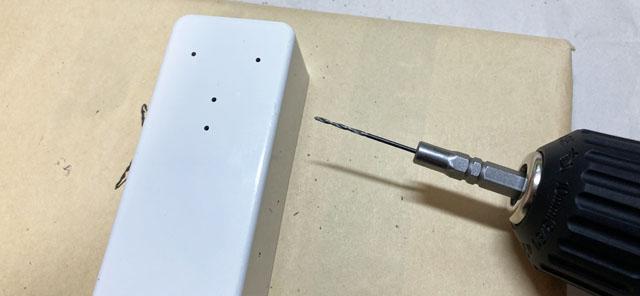
In order to accurately drill the hole position with an electric hand drill, I first used a pointed screwdriver to dent the center of the hole position. After that, I made a hole with a 1.2mm drill by aligning the tip of the drill with the dent. Next, I widened this hole from 1.2mm to 3mm, and then widened from 3mm to 6mm. This allowed me to drill the hole in the correct position. Since the mounting holes for jacks and pots are larger than 6 mm, I used a taper reamer to widen the holes and fit them to the size of the holes in each part.
Placement in the enclosure
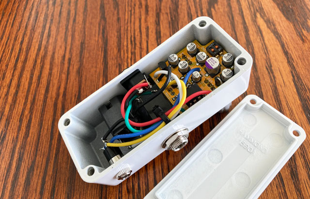
The layout image of the parts and boards in the enclosure is shown below.
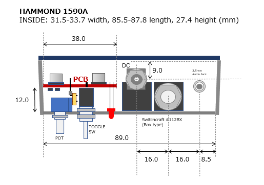
Pot height adjustment
After drilling holes in the enclosure, I did the following in order to match the height of the toggle switch and the pot.
1) Solder the toggle switch to the board.
2) With the pot lead inserted in the hole in the board, attach the toggle switch and pot to the enclosure and lightly tighten the nut.
3) In this state, solder the pot leads.
4) Remove the tightened nut and remove the board.
The pot and toggle switch are now attached to the board at the same height. Similarly, the LED was soldered later.
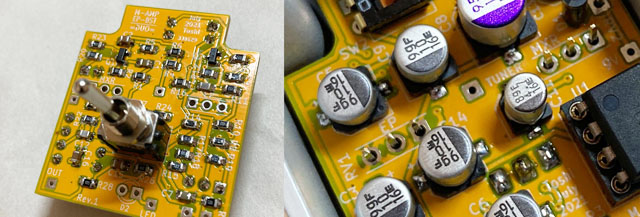
Check operation
Before incorporating it into the enclosure, I confirmed the operation with only the board. As usual, I generated a sine wave with free software on my PC and input the signal from the audio interface box (steinburg UR22mkII) to the board.
By inserting the wire from the PCB into the breadboard, I connected the signal input/output and the battery to the PCB.
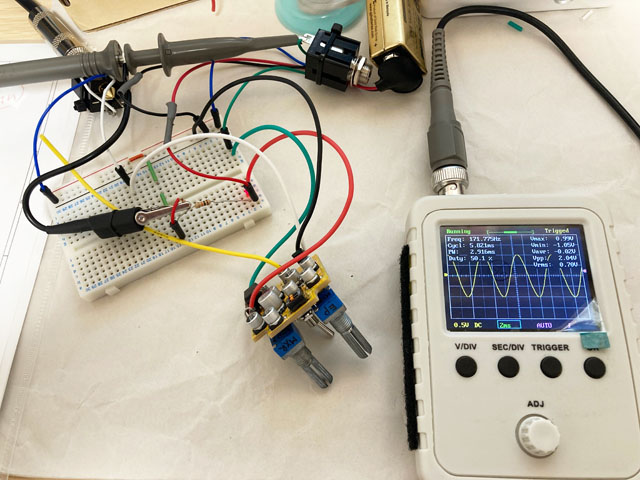
This time it worked fine with no mistakes
This time, there were no mistakes in the circuit or mounting, and it worked fine. The direction of rotation of the pot and the direction of the toggle switch were also perfect.
Sound output characteristics
I checked the sound output of the two amplifiers while switching the toggle switch. I didn't expect the characters to be so different. It would have been nice if it could be switched with a foot switch instead of a toggle switch.
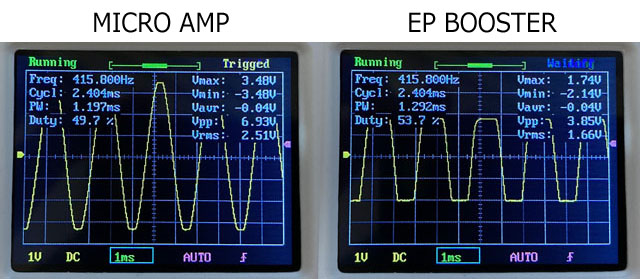
When observing a sine wave with an oscilloscope, MICRO AMP has a wide dynamic range and does not distort up to around 3.5V, but EP BOOSTER (only my own work?) begins to distort around 1.6V.
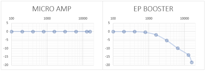
As for frequency characteristics, MICRO AMP is flat from 50HZ to 16kHz and is an ultra-pure amplifier characteristic. For EP BOOSTER, when both DIP SWs were turned off (brightness off), the gain started to decrease around 1kHz and became -6dB around 4kHz. However, it feels like the sound is getting thicker, not just the high frequencies going down. The frequency characteristics are as shown in the figure below, but I presume that the phase change due to the CR filter and the narrow dynamic range (easily distorted) are the factors that make the sound thicker.
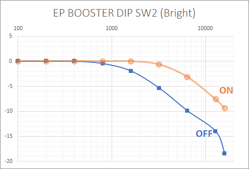
We also confirmed the change in the DIP SW of EP BOOSTER. It seems that SW1 is a BASS boost, but when it is turned on, 50Hz or less is raised by about 1dB, but there is almost no change in hearing.
SW2 is a bright switch. Here, the characteristics of the treble change, and it certainly becomes bright. When asked which one I like, I prefer OFF, which has a mellow tone.
Sound samples
This is a sample when playing a chord with a clean tone. MICRO AMP is a HiFi-like, ultra-flat sound that does not deform in any frequency band. On the other hand, EP BOOSTER (both DIP SW is OFF) has rich bass and midrange. I feel the image of the guitar sound coming out in front.
The same phrase will be played twice. The first half is MICRO AMP and the second half is EP BOOSTER. Both GAINs are the minimum (around 0 dB). A thin reverb has been added in the DAW.
![]() Fender Stratocaster Mid Pickup Rhythm Guitar (MP3)
Fender Stratocaster Mid Pickup Rhythm Guitar (MP3)
![]() Gibson Les Paul Front Pickup Solo (MP3)
Gibson Les Paul Front Pickup Solo (MP3)
The recording environment is:
Guitar (Stratocaster / Les Paul) -> Self-made buffer pedal -> MOOER Preamp006 (Fender blues deluxe clean, cabinet ON) -> UR22mkII -> DAW (Studio One)
Completed by incorporating into enclosure
Create an original sticker
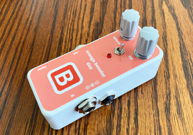
I used a white painted enclosure. I wanted to make it look like a commercial product, so I put a sticker on the top of the enclosure. The design image made with Power Point software was printed on a sticker paper with an inkjet printer and cut out with a cutter. Holes such as pots are cut out with a cutter according to the holes after pasting the created sticker.
I designed it in orange and named it "orange booster duo".
The beautiful "Orange Booster Duo" is completed!
The sticker on the top is nice. I am excited to make elaborately designed stickers next time.
Things to think about after making this booster: I / O impedance and TRUE BYPASS
Boosters and buffers not only make the sound louder, but also affect the output impedance of the guitar pickup, which can significantly change the character of the sound. "TRUE BYPASS" is generally said to be good because it allows the signal to pass through, but the impedance of the signal changes each time the effect pedal connected in series is turned ON / OFF. Therefore, if you connect an effect pedal that makes a good sound to another pedal, the sound will often change at all.
"Holistic Tonal Solution" is introduced in the explanation of the switcher of Japanese pedal maker "FREE THE TONE". This is a technology that keeps the input / output impedance of each loop constant (input 1 MΩ, output 200 Ω) regardless of whether the loop is ON or OFF. Certainly, the switcher is responsible for turning the pedal on and off, so I think it's a good idea.
BOSS pedals are turned on and off with FET electronic switches, and all products are buffered, not TURE BYPASS. Therefore, I imagine that the BOSS method has a smaller effect on the tone when the pedals are connected in series.
Until now, I have made clones and modifications of ready-made pedals by myself, but I think it would be good to put a circuit that makes the input and output impedance the same regardless of ON / OFF in each pedal.
Language
Self-made
effect pedals
- Pedals list page
 Tool selection
VEMURAM Jan Ray
Xotic BB preamp
Klon Centaur
 Revived old Chorus
 MXR Envelop Filter
 BBD Analg Delay DM-3
 600ms Analog Delay
 Arduino Analog Delay
 BBD Analg Chorus CE-3
CMOS Octaver OC-2
 Riot using chip parts
 Original design noise gate
 EP & MICRO AMP duo
 Keeley 4 Knob Comp
 MXR Phase 90 MOD
 Keeley Blend Comp
 DM-3 longer delay time
 ISP Decimator V2164


