MIDI control of effect pedals with Arduino
Self-made Guitar Effect Pedals
Explore the articles to learn more about your favorite effect pedals.
|
Switching effect pedal parameters via MIDI
MIDI is a standard that was published in 1981, more than 40 years ago. It connects with a 5-pin DIN connector and transfers data with a low-speed serial signal of 31.25 Kbps. Although it is an outdated interface now, it is still used as standard in instruments and equipment.
Some high-performance effect pedals can receive MIDI signals and switch presets and parameters. Some high-end pedal switchers also have a MIDI signal output function, and can send a MIDI signal at the same time as switching the connection of the pedal, such as changing the delay time of a digital delay with MIDI function.
Therefore, assuming an effect pedal that can change internal parameters by receiving MIDI signals, I first tried making a MIDI interface with Arduino to confirm the feasibility.
Used an Arduino MEGA 2560 compatible board
For the Arduino board, I used an Arduino MEGA 2560 compatible board. This was simply because real Arduino boards were expensive. I bought an "ELEGOO" board on Amazon for almost half the price. As far as I've used it, it's fully compatible with the real one.
The MEGA 2560 has 3 sets of serial ports (RX/TX). RX0/TX0 are used to interface with the PC for program transfer, so I used RX1/TX1 (defined as "Serial1" in Arduino) for sending and receiving MIDI signals this time.
This time, I used this large board for the purpose of confirming the feasibility, but when I actually incorporate it into the effect pedal, I will use a smaller module.
MIDI interface circuit
A 5-pin DIN connector is used for MIDI connections. The MIDI signal reception (RX) part is designed to be electrically insulated from the connected instrument or equipment. Therefore, in general, an opto-isolator (photocoupler) is used to electrically isolate the circuit. The purpose of this specification is to prevent ground loops and signal loops when electronic musical instruments are interconnected.
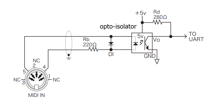
The figure below is the receiving part (MIDI-IN) of the standard circuit listed in the MIDI specifications. You can see that it is not electrically connected to the inside of the device.
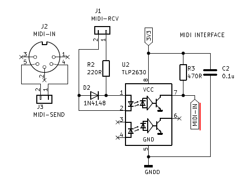
Since MIDI signals are slow, a general-purpose photocoupler will work well. This time, I used "TLP2630" which I could purchase by mail order. The output has an open-collector transistor buffer. It has two circuits, but I'm only using one.
Operation check and result
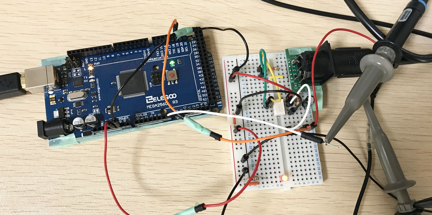
MIDI interface circuit, Audiino connection
I used the standard circuit of the MIDI specification as it is and connected it to "RX1" of the Arduino board.
Arduino MIDI test program
A test program that generates pulses for the number of times corresponding to the first numerical value among the two parameters in MIDI when receiving a MIDI program change command (0xC*, * is the MIDI channel) in order to check the internal operation.
The Arduino source code is posted on this page.
MIDI command transmission software
Using free PC software that can easily transmit MIDI data, I output from the MIDI-OUT of the audio interface (Steinberg UR22mkII).
[Transmitted MIDI signal]
MESSAGE: 0xc0 -> program change (0xc0)
CHANNEL: 0x00 -> MIDI Ch1
VALUE1: 005 -> 1st parameter (5)
VALUE2: 000 -> second parameter (unused)
Execution result
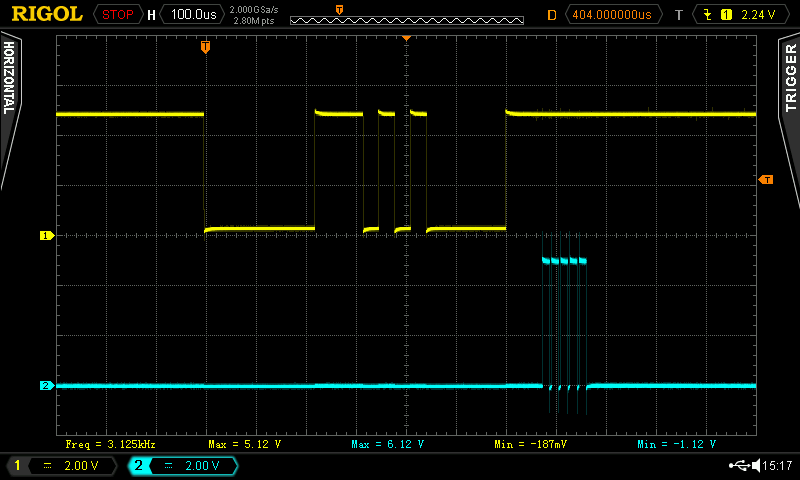
The waveforms of RX1 (MIDI serial, yellow) and A7 (pulse output, blue) monitored with an oscilloscope are shown below. You can see that the first parameter "005" sent is received and five pulses are generated.
Future Plans
So far, I have confirmed that I can easily control effect pedal parameters by receiving MIDI signals sent from a switcher, etc., using an Arduino.
In the future, I'm planning to create an analog delay that can be controlled via MIDI/WiFi, along with the "WiFi control of effect pedals with Arduino/ESP32C3" introduced on another page.
Language
Self-made
effect pedals
- Pedals list page
 Tool selection
VEMURAM Jan Ray
Xotic BB preamp
Klon Centaur
 Revived old Chorus
 MXR Envelop Filter
 BBD Analg Delay DM-3
 600ms Analog Delay
 Arduino Analog Delay
 BBD Analg Chorus CE-3
CMOS Octaver OC-2
 Riot using chip parts
 Original design noise gate
 EP & MICRO AMP duo
 Keeley 4 Knob Comp
 MXR Phase 90 MOD
 Keeley Blend Comp
 DM-3 longer delay time
 ISP Decimator V2164


