WiFi control of effect pedals with Arduino/ESP32C3
Self-made Guitar Effect Pedals
Explore the articles to learn more about your favorite effect pedals.
|
Control amps and effectors from iPhone or PC
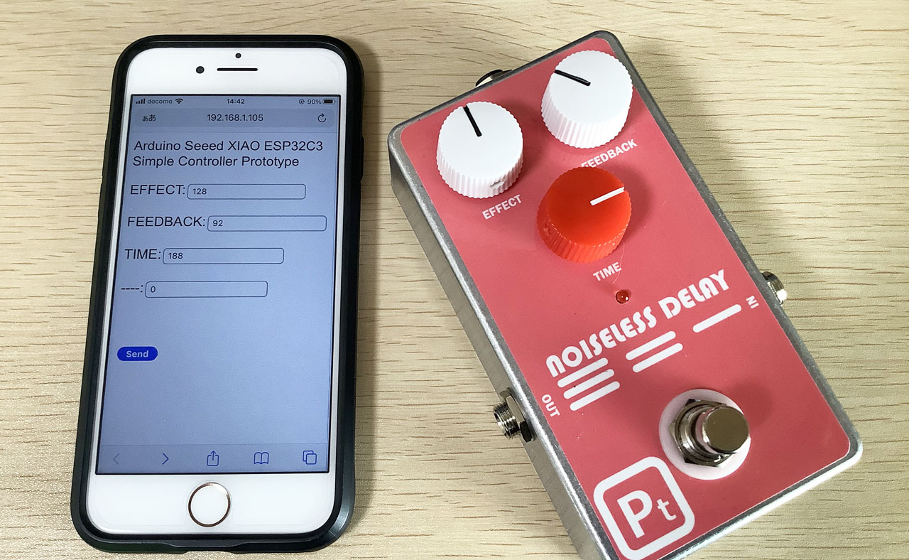 Recently, products that allow you to operate the knobs of amplifiers and effectors from a PC, iPhone, or iPad have appeared. You can change the sound of the actual amp or effect pedal by entering numerical values on the screen of your iPhone or PC, or by turning the knobs on the screen.
Most actual products do not operate analog circuit variable resistors, but are designed to operate DSP (digital processor) parameters with software. Many products are made up of a combination of a microcomputer (ARM Cortex series) and a DSP (Analog Devices SHRAC).
I have built many analog guitar effect pedals. Analog effect pedals change the sound by turning a variable resistance (volume) knob. So, using a microcomputer board, I tried to control the volume knob of an analog effect pedal from an iPhone or PC.
Control effect pedals with Arduino
 Arduino is an easy-to-program, library-rich development environment. The CPU boards on the market come in a wide variety of combinations of microcontrollers and peripherals, so you can choose one according to your purpose, and the price is very low.
This time, I tried using the board "Seeed XIAO ESP32C3" for IoT that can be programmed with Arduino and has WiFi.
The CPU uses the open source "RISC-V 32bit" and operates at 160MHz.
It was only $8 at Akizuki Denshi Tsusho in Akihabara.
Effect pedal WiFi controller configuration
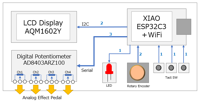
I configured the system using Seeed XIAO ESP32C3, character display, rotary encoder, tact switch and digital potentiometer (digital volume). Since the ESP32C3 has only 11 I/O pins, the number of connection lines with each device is shown in the figure, considering the I/O allocation.
Feasibility study
Tried on breadboard
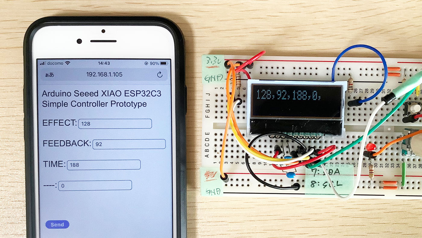
In order to confirm whether it can actually be realized, I assembled it on a breadboard and tried it while writing a program in the Arduino development environment. The ESP32C3 setup method and a sample for blinking the LED are posted on the website of the developer, Seeed, so it was easy to start.
Since the ESP32C3 is an IoT board, it is very small, about the size of a coin. There is a very small terminal for the WiFi antenna, and a sheet antenna is also attached. An antenna conductor is printed on a black square sheet. I haven't measured the sensitivity, but I can send and receive WiFi with this antenna without any problems.
LCD character display
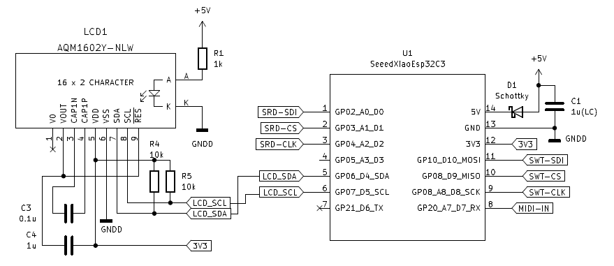
I used a 16-character x 2-line LCD character display (AQM1602Y) to see the parameters. It can be used simply by connecting the "SDA" and "SCL" terminals of the ESP32C3. The 3.3V power supply output by ESP32C3 can be used as is.
The Arduino display library "ST7032" has been posted, and the built-in characters can be easily displayed. The circuit can be simplified because the contrast is set by command. However, if the contrast value is wrong, the characters cannot be seen at all.
Implement WebServer on Arduino
In order to control it from an iPhone or PC via WiFi, I implemented a WebServer (HTTPD) on the ESP32C3, and passed parameters such as the volume of the effect pedal to the ESP32C3 from the web browser on the iPhone or PC.
Arduino has a simple WebServer sample named "HttpServerUpdater", which I could use almost as is. If you access the ESP32C3's IP address (assigned by your home WiFi router) with http and send parameters from the browser with POST or GET, you can receive it with the ESP32C3.
The WiFi library has mDNS (Multicast Domain Name System) function, so if you register "nld" as the board name, you can access the board with "http://nld.local" instead of IP address.
[Operation sequence]
(1) Triggered by root access from the browser, send the characters of "parameter setting page (HTML)" stored in the array in ESP32C3 to the browser
(2) Set the parameters in the "Parameter setting page (HTML)" on the iPhone browser and send POST/GET (submit)
Example) http://esp32.local/setvol?v1=128&v2=92&v3=188
(3) ESP32C3 WebUpdater receives "setvol?v1=128&v2=92&v3=188"
(4) Parse the parameters (v1=128&v2=92&v3=188) and display them on the LCD
(5) Send serial data to the digital potentiometer to set parameters and change resistance values
Reference: Arduino source code (To be prepared)
Page data to be displayed on the web browser (index_html.ino)
Arduino program (ESP32C3_HTTPD.ino)
Digital potentiometer to control analog circuit
Uses Analog Devices "AD8403ARZ100" for variable resistance
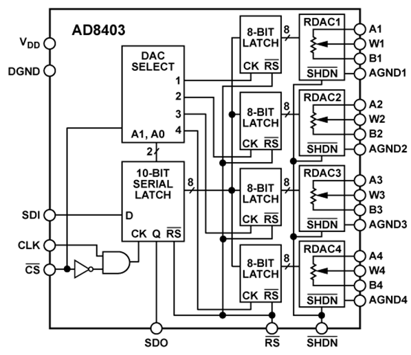
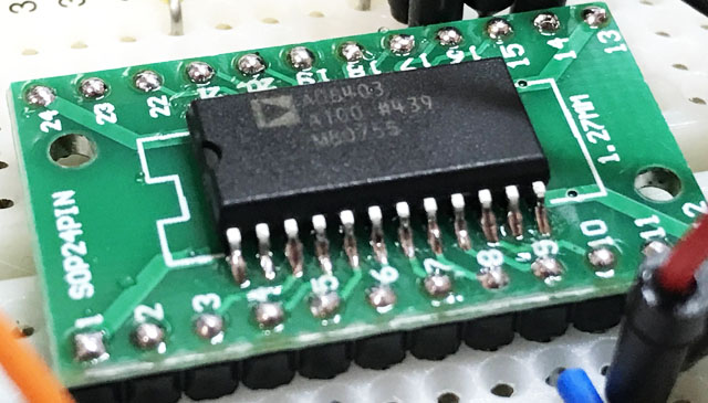 I used Analog Devices' AD8403ARZ100 for the digital potentiometer. There are four variable resistors of 100 kΩ in this, and the resistance value can be changed in 256 steps. The i/o is 3-wire serial.
If the volume of an analog effect pedal is connected to this variable resistor, the ESP32C3 can be used to adjust the amount of effect.
However, the power supply voltage of this chip is up to 5.5V, so it may be necessary to adjust the voltage range to match the circuit of a 9V effect pedal.
Arduino SPI (Serial Peripheral Interface) operation
I checked the serial signal output using the SPI function of the Arduino. I used the pins "MOSI, MISO, SCK" for serial on the XAIO ESP32C3 and the standard "SPI" for the software library. The screen below shows the 2-byte data required for the digital potentiometer AD8403.
  // SPI setup
  SPI.begin();
  pinMode(SPI_SS, OUTPUT); // SPI_SS -> D9
  digitalWrite(SPI_SS, HIGH);

  // ditital pot SPI
  digitalWrite(SPI_SS, LOW);
  SPI.transfer(ch);
  SPI.transfer(encoder_newPos);
  digitalWrite(SPI_SS, HIGH);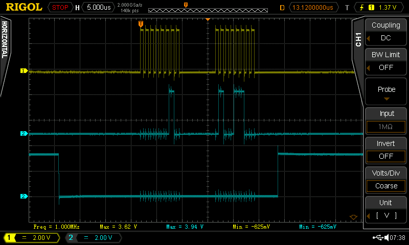
From top to bottom: CLK, SDI, /CS
(Since the oscilloscope I have is 2ch, the two blue waveforms below are photoshopped.)
Operation of Digital Potentiometer AD8403
I connected the serial output mentioned above to the AD8403 and checked the operation. The AD8403 power supply is 5V, but the serial coming from the ESP32C3 is 3.3V. The AD8403 specification says that the digital logic threshold is 2.4V, so I connected it as is. It worked fine.
The AD8403 I purchased is a version with a variable pot resistance of "100kΩ". The number of variable steps of resistance is 256, so if you send 127 in serial, it should be 50kΩ.
The picture below shows the resistance value measured with a tester when "127" and "63" are sent to the resistance parameter of the AD8403. I found that the resistance varies linearly according to the parameters.
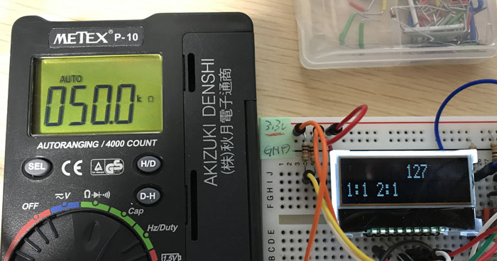
When sending "127"
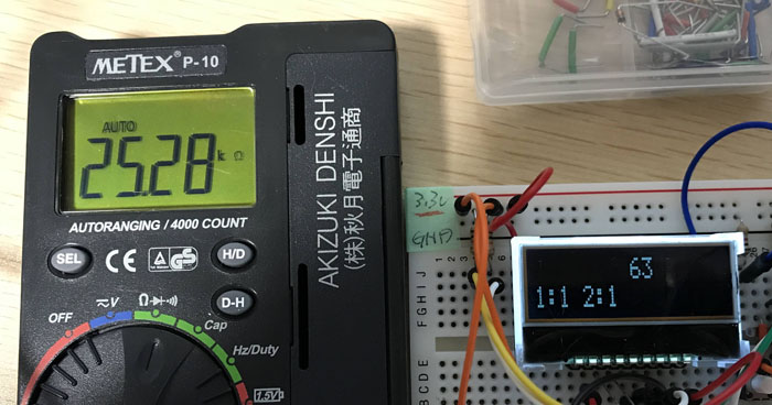
When sending "63"
Future plans
I was able to confirm the feasibility of WiFi. In the future, I would like to think of a system that controls analog pedals with both WiFi and MIDI. I would also like to implement parameter change using MIDI signals, which I confirmed on another page, "MIDI control of effect pedals with Arduino".
In addition, I'm planning to build a PCB and build a pedal that can control delay time, feedback and effects level based on my recent "noiseless delay using PT2399".
Language
Self-made
effect pedals
- Pedals list page
 Tool selection
VEMURAM Jan Ray
Xotic BB preamp
Klon Centaur
 Revived old Chorus
 MXR Envelop Filter
 BBD Analg Delay DM-3
 600ms Analog Delay
 Arduino Analog Delay
 BBD Analg Chorus CE-3
CMOS Octaver OC-2
 Riot using chip parts
 Original design noise gate
 EP & MICRO AMP duo
 Keeley 4 Knob Comp
 MXR Phase 90 MOD
 Keeley Blend Comp
 DM-3 longer delay time
 ISP Decimator V2164


