Self-made analog cabinet simulator for recording at home
Self-made Guitar Effect Pedals
Explore the articles to learn more about your favorite effect pedals.
|
Analog cabinet simulator with a wide range of adjustment
Until now, I have used "MOORE Micro Preamp 006" for the final part of the pedal board for recording at home. This pedal seems to be simulating Fender Blues Deluxe. I have used it as a cabinet simulator without using the distortion of the preamp section.
The undistorted sound of this MOORE simulator is a very clean sound, but it may be a little less powerful. I've never used a real amp, so I'm not sure if MOORE is similar.
When I record at home, if I use the TONE of the guitar at full 10, the sound becomes thin, so I use the TONE of the guitar at a low level or add an EQ that cuts the high range with DAW after recording.
Recently, digital equipment that reproduces the characteristics of a cabinet by convoluting IR (impulse response) has become popular, but simulation of frequency characteristics can be realized with a simple analog filter circuit. I have been sticking to analog to make pedal boards, so at this time I decided to make an analog cabinet simulator with a wide adjustment range.
Looking for a cabinet simulator circuit
Many circuits can be found on the Internet that resemble the characteristics of Marshall cabinets. For example, "Condor Cab Sim" seems to resemble a Marshall speaker. It has peaks at around 100Hz and 3k, valleys at around 400Hz, and cuts above 3kHz at around -12dB / oct.
I found a "Multicab Sim" with 4 adjustment points on this circuit. Although it is different from EQ, it is designed so that the characteristics of TOP (HIGH), BOTTOM (LOW), FLATNESS (MID), and GAIN can be changed with 4 pots. Since the adjustment range seems to be wide, I decided to make it with this circuit.
Circuit diagram
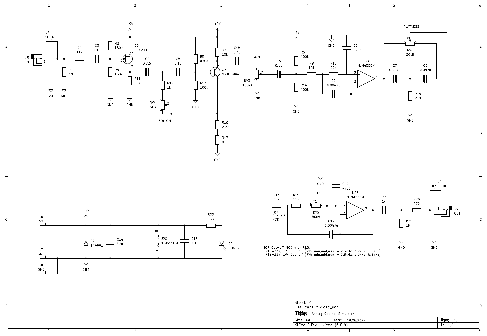
I designed the circuit based on "Multicab Sim". For the input section, I wanted to increase the input impedance and added a JFET buffer so as not to affect the HPF (C4, R12, VR4) characteristics of the first stage. Moreover, the protection resistance of 470Ω is added to the output.
In addition, the Q3 gain amplifier has a gain of +12 dB in the original circuit. However, since this constant is easily distorted, the gain is reduced by adjusting the constant to about +7 dB. Others remain original.
Designed the PCB to fit in a mini-sized enclosure
Using surface mount components
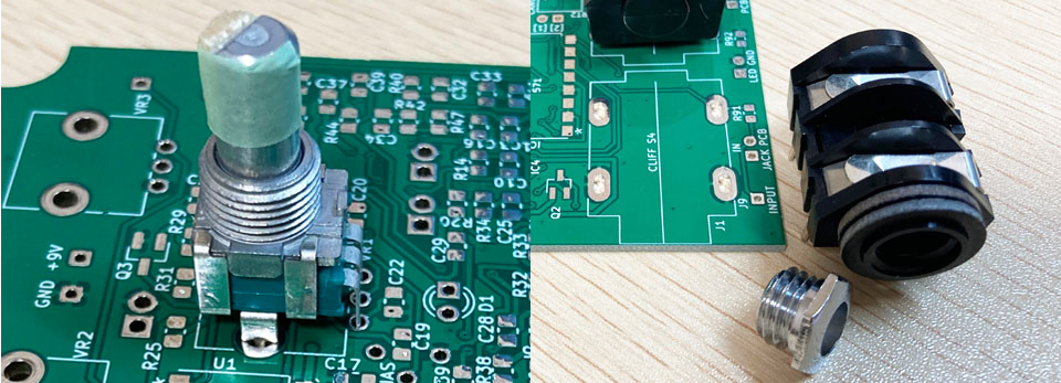
Made with surface mount parts to fit in the same mini size enclosure (HAMMOND 1590A) as MOOER. For the pod, I used a pot for PCB mounting (ALPS RK09L series, purchased from Sengoku Densho).
If it is difficult to attach the pot directly to the board, or if parts are not available, you can also make it using a universal board and an L-shaped pin header. (Refer to article here.)
I don't usually connect to a guitar amplifier, I always connect directly from the pedal board to the audio interface, so I omitted the footswitch. Instead, an input / output phone jack (CLIFF S4 / MBB / PC-C) was mounted on the PCB.
Design a PCB using KiCAD
Again, I made a PCB to mount surface mount chip components. I designed a double-sided PCB using "KiCAD". Pots and phone jacks are not available in the KiCAD library, so I create and use footprints (shape data of parts) myself.
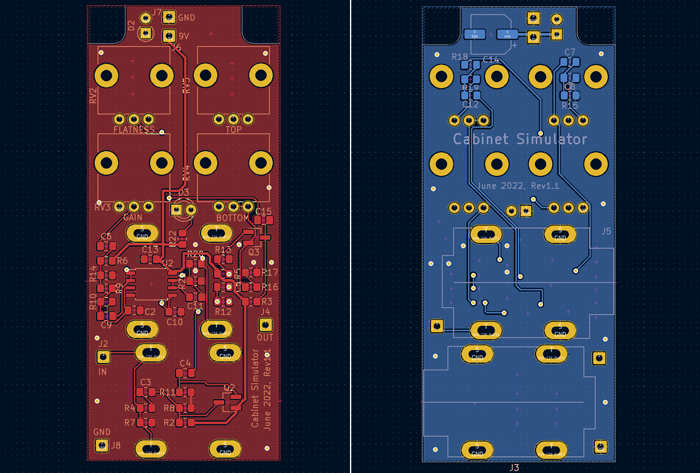
Double-sided trace
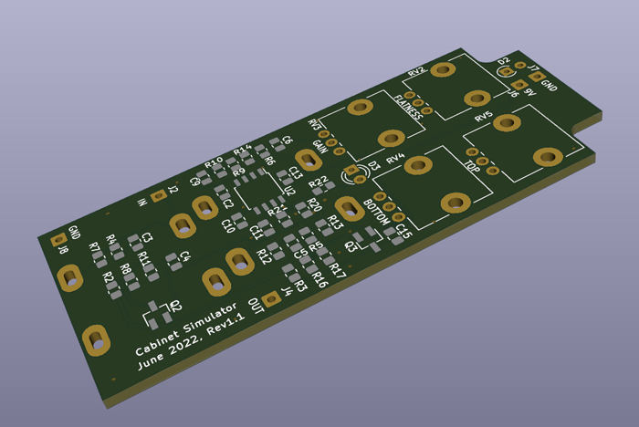
KiCad 3D view image
KiCad PCB design data
The PCB data created using "KiCad (Windows 64-bit) Version: (6.0.4), release build" is provided. The ZIP file contains the schematic, board design data, and original component data. Please read the terms of use and disclaimer in the attached "readme.pdf" before using this data.
PCB manufactured by "PCBgogo"
This time, I tried using "PCBgogo" which manufactures PCB within "24 hours".
To place an order for "PCB go go", just register the Gerber data. When I placed an order, it was actually manufactured and shipped in 24 hours as expected. I tried using "OCS" for this international courier service. This company is a service that provides international home delivery in partnership with the Japanese airline company ANA. It is attractive that the shipping fee is cheaper than DHL. Delivery time was the same as DHL delivery as we ordered on Sunday afternoon and arrived on Saturday morning of the same week.
The quality of the board was excellent and the silk print I was worried about was printed clearly and there was no problem at all.
The cost of manufacturing a PCB go go is $ 5 for 10 pieces. Even including the OCS shipping fee of $ 15 (DHL is $ 20), I was able to produce it for $ 20.
Hand-soldering with chip parts on the board
The surface mount parts are really small, and it is a soldering work using tweezers. I'm used to it, but I think this task is quite difficult for people with old eyes like me. But it's fun work.
The phone jack is a CLIFF board mount type described above and must be soldered to fit the inner width of the enclosure. HAMMOND's enclosure expands in size by about 2mm toward the lid (trapezoidal), so I made the lead hole longer in consideration of the error. The soldering was done after inserting the jack into the board, actually fitting it to the enclosure, and deciding the just position.
Operation check
Since this self-made product has few parts, it worked in one shot without any soldering defects or PCB design mistakes.
Changes in the characteristics of adjustment points
The adjustment points of this circuit diagram are as follows.
TOP: HIGH cutoff frequency is variable in the range of 2kHz to 4kHz
BOTTOM: LOW cutoff frequency is variable in the range of 50Hz to 120Hz
FLATNESS: The depth of the valley at the center 500Hz is variable in the range of -12dB to + 6dB.
GAIN: Level control
The graph below shows the actual frequency characteristics measured with a sweep sign signal using the free software "Room EQ Wizard (REW)" after the completion of this cabinet simulator.
Based on the one with all pots in the center (it seems to be Marshall characteristics), each adjustment point was changed to the minimum and maximum for measurement.
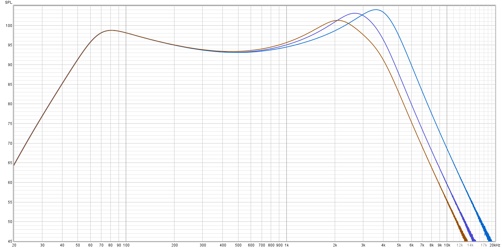
TOP: HIGH cutoff frequency is variable in the range of 2kHz to 4kHz (Marshall simulation is 3kHz in the center)
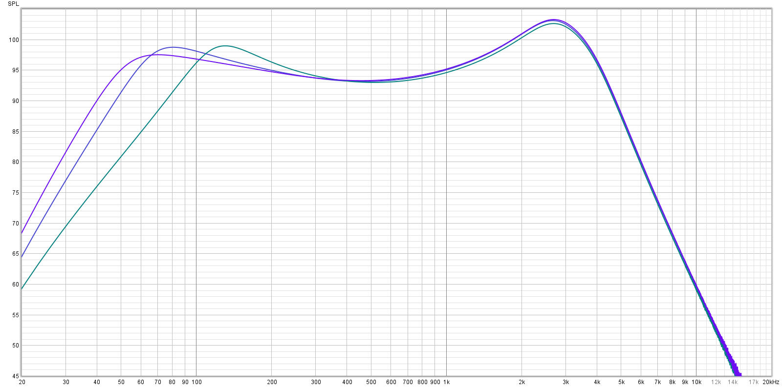
BOTTOM: LOW cutoff frequency is variable in the range of 50Hz to 120Hz (Marshall simulation is 70Hz in the center)
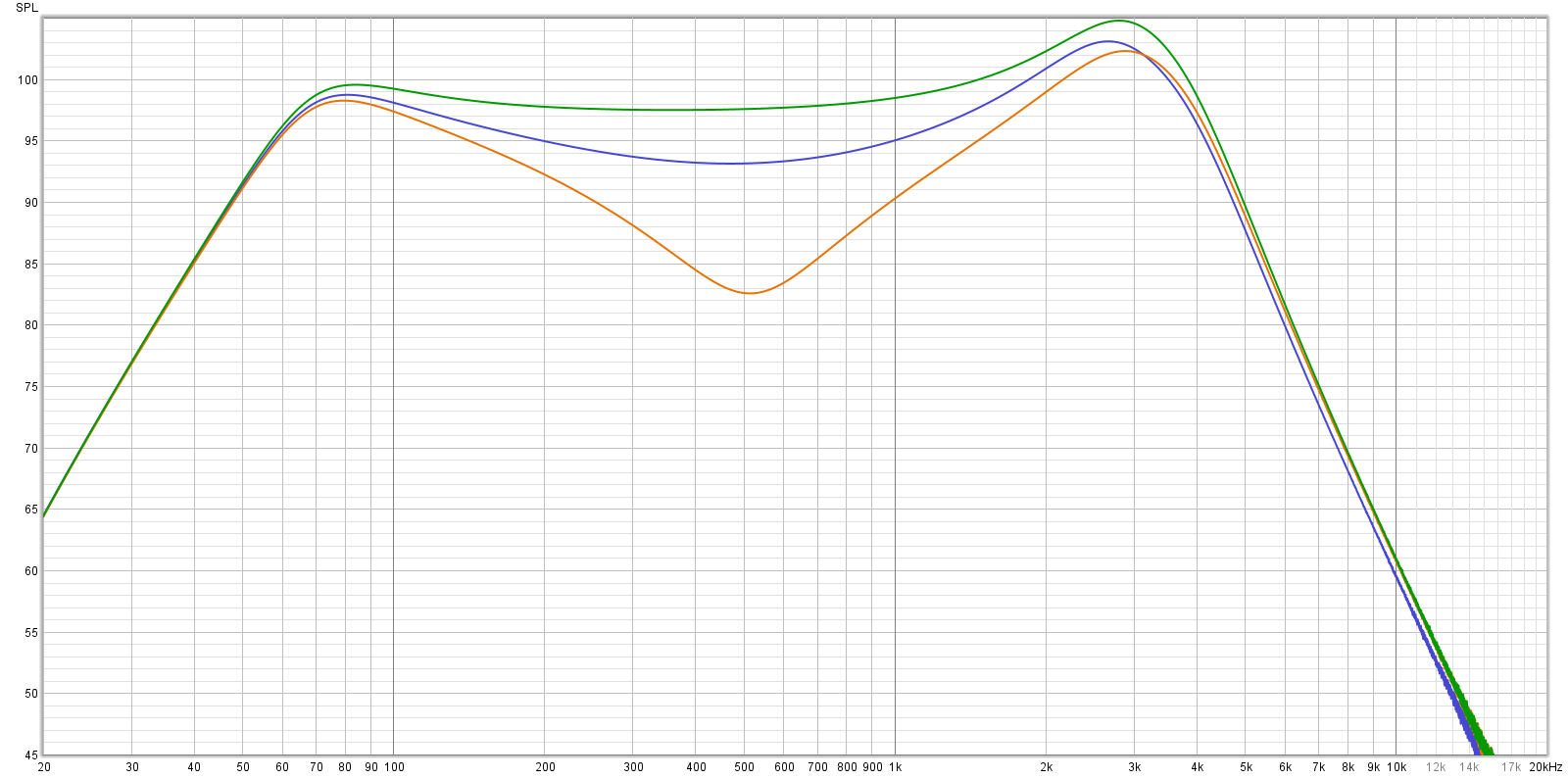
FLATNESS: The depth of the valley at the center 500Hz is variable in the range of -12dB to + 6dB (Marshall simulation is 0dB in the center).
(Reference) Characteristics of "MOORE Micro Preamp 006"
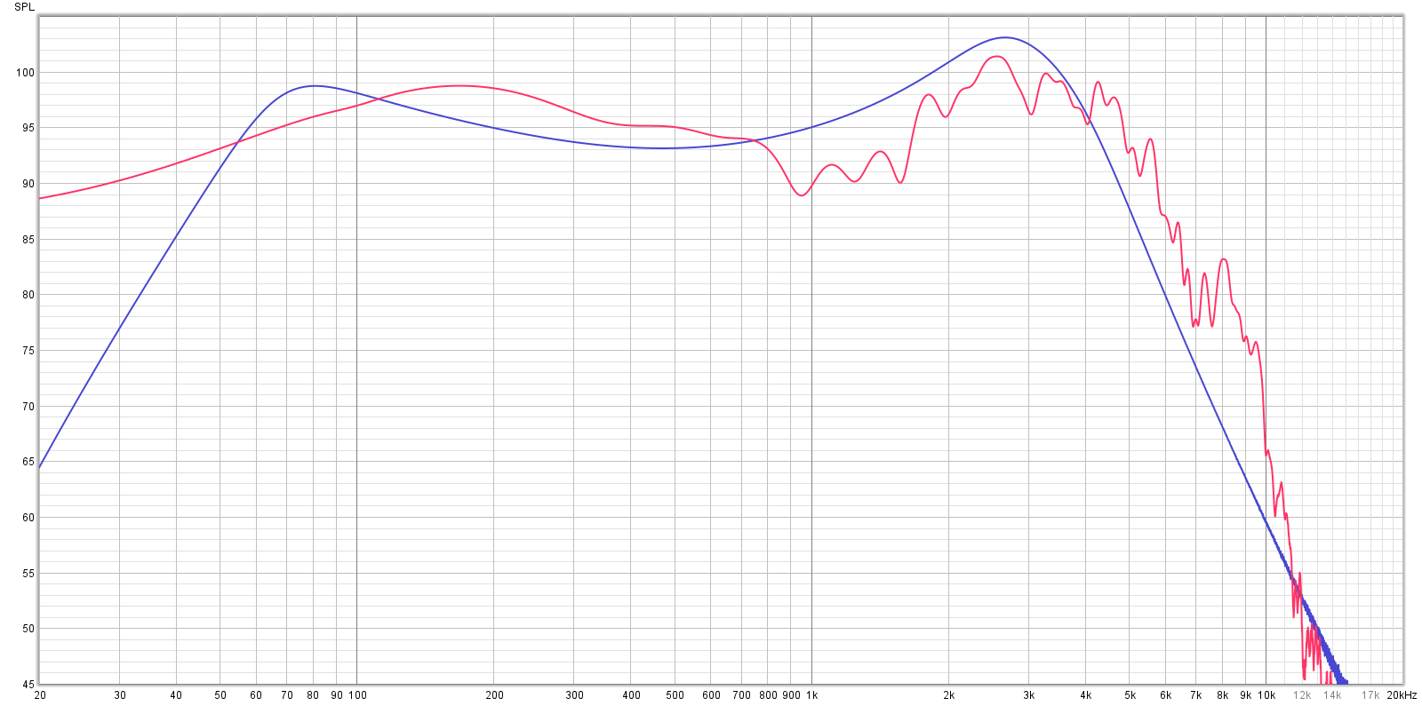
By the way, I also measured the characteristics (graph: red) of the "MOORE Micro Preamp 006" that I have been using so far, which seems to be simulating Fender Blues Deluxe. TONE is all in the center and GAIN is 0. I compared it with the characteristics of the cabinet simulator I made (graph: blue). MOORE seems to be digitally convolving IR, and the characteristics of high frequencies are rough. There may be elements of presence that give a feeling of air (delay from speaker to microphone, reverberation) in IR.
As for the difference in characteristics, MOORE has a wider high range, so this may be the reason why the sound is clear and light. The low range includes 50Hz or less, but I don't think that the actual speaker of Fender will produce such a low sound (heavy bass), so this is an error in the convolution calculation due to the shortness of the IR samples.
Processing of enclosure
This time, pots, LEDs, and phone jacks are all mounted on the board, so it is necessary to drill holes accurately according to the position of the parts. I put the board on the enclosure and marked the hole position so that I could get the position surely. The height of the jack on the side was carefully determined by referring to the dimensional drawing of the pot, the thickness of the board, and the dimensional drawing of the jack.
After deciding the center position of the parts to be attached, dent the center of the hole with the center punch so as not to shift the hole position, then first make a small hole with a 1.2 mm drill around the dent, 1.5 mm, 2 mm , 2.5mm, 3mm ... 6mm drills gradually widened the holes. 6mm or more is widened with a hand-type taper reamer.
The LED was soldered after making a hole in the enclosure. First, I passed the LED lead through the board, temporarily fixed the pot and jack to the enclosure, made the LED head come out from the hole in the case, checked the height of the LED, and then soldered it.
The guide rail on the lid of the enclosure has hit the part
The mini size enclosure (HAMMOND 1590A) has a height inside dimension of 27 mm. If the pot is mounted on the back of the board and the jacks are mounted on the front of the board, the total height of all heights is about 26 mm, so it fits perfectly.
When I actually mounted the parts on the board and attached them to the enclosure, the guide rail inside the lid hit the upper part of the phone jack and DC jack, and the lid could not be closed. I used an iron scraper to scrape the guide rails that hit the phone jack and DC jack. Since the enclosure is made of aluminum, it can be scraped, but it took a long time.
Completed "Cabinet Sim" by incorporating it into the enclosure
I put a sticker on the top of the enclosure. I used an inkjet printer to print a design image created using Power Point on sticker paper and cut it out. Holes such as pots are cut out according to the holes after attaching the sticker to the enclosure.
Sound samples
These are samples of the outro solo of my original song "Thinking About You" by changing the position of the knob in the following environment. I think each person feels it differently, but I think that the sound with the TOP raised slightly (sample B) is close to the sound of a guitar amplifier that I'm used to hearing.
The change in sound due to the adjustment of each knob feels as follows.
TOP: When raised, the distortion tingling sound becomes more noticeable, and it gets closer to the sound of small speakers.
BOTTOM: When using headphones, changes in sound cannot be recognized. Even with Max, there is no feeling that the bass is boosted.
FLATNESS: When raised, it makes picking more powerful and chunky.
GAIN: Only it changes in volume and does not affect the characteristics.
Recording environment: Fender Stratcaster (mid single) -> Self-made EP Booster -> Self-made Keeley Comp Direct Mix -> Self-made BB-Preamp -> Self-made Cabinet Sim -> UR22mkII -> DAW (Studio One 5)

![]() Clean phrase, Mid single pickup (MP3)
Clean phrase, Mid single pickup (MP3)
Recording environment: Fender Stratcaster (rear hum) -> Self-made EP Booster -> Self-made ISP noise reduction -> Self-made BB-Preamp -> Self-made Cabinet Sim -> UR22mkII -> DAW (Studio One 5)

![]() Overdrive phrase, Rear hum pickup(MP3)
Overdrive phrase, Rear hum pickup(MP3)
Modify the TOP LPF cutoff frequency
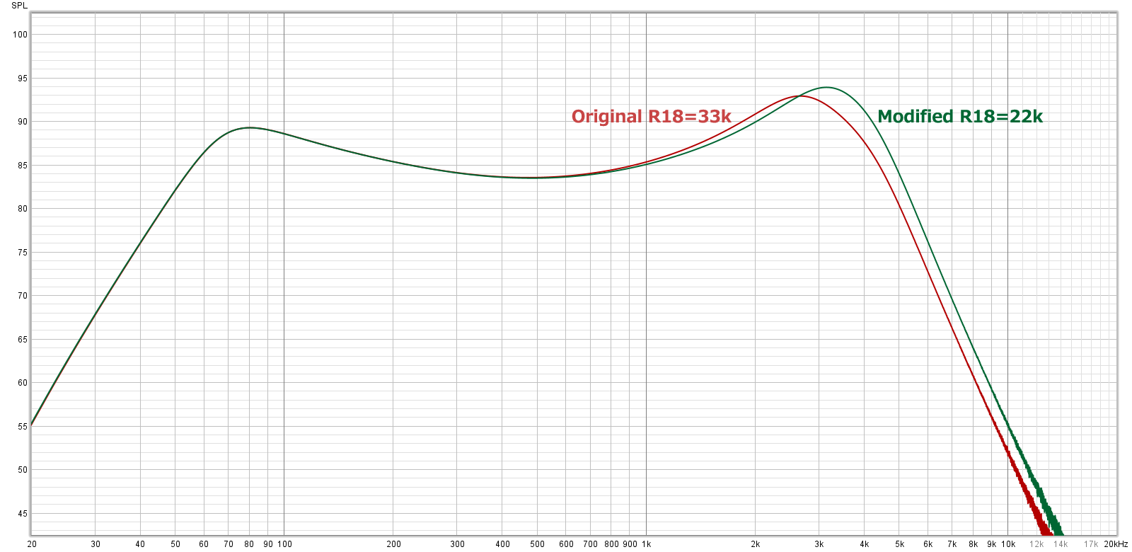
The original circuit seems to simulate a large Marshall cabinet, but in my recording at home, I wanted a little more high frequencies. Especially for clean rhythm cutting with only the compressor pedal, I wanted the metallic feel of the strings. Therefore, I made a modification to raise the LPF (low pass filter) cutoff of TOP.
I used the page of this site to calculate the resistance value.
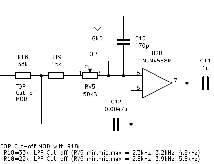
Technically, I changed a part of the resistance (R18) value of the LPF (secondary Sallen-Key Low-pass Filter) composed of the operational amplifier in the final stage to raise the cutoff frequency slightly.
I will squeeze the TOP (High) knob when using distortion, and I will raise the TOP (High) knob when I want a clean tone and a metallic feel.
The graph below shows the difference in frequency characteristics when all knobs are centered.
Afterword
The analog cabinet simulator I made this time is based on the Marshall characteristics. My purpose of using this simulator is to make it sound that is not buried in the sound of the whole song when used in recording at home, so I would like to explore the combination of the simulator's adjustment knob and DAW's EQ.
My latest pedal borad can be seen here.
Language
Self-made
effect pedals
- Pedals list page
 Tool selection
VEMURAM Jan Ray
Xotic BB preamp
Klon Centaur
 Revived old Chorus
 MXR Envelop Filter
 BBD Analg Delay DM-3
 600ms Analog Delay
 Arduino Analog Delay
 BBD Analg Chorus CE-3
CMOS Octaver OC-2
 Riot using chip parts
 Original design noise gate
 EP & MICRO AMP duo
 Keeley 4 Knob Comp
 MXR Phase 90 MOD
 Keeley Blend Comp
 DM-3 longer delay time
 ISP Decimator V2164


