[Latest!] Presettable BB-Preamp distortion pedal using Arduino
Self-made Guitar Effect Pedals
Explore the articles to learn more about your favorite effect pedals.
|
BB-Preamp, practical distortion pedal with a wide adjustment range
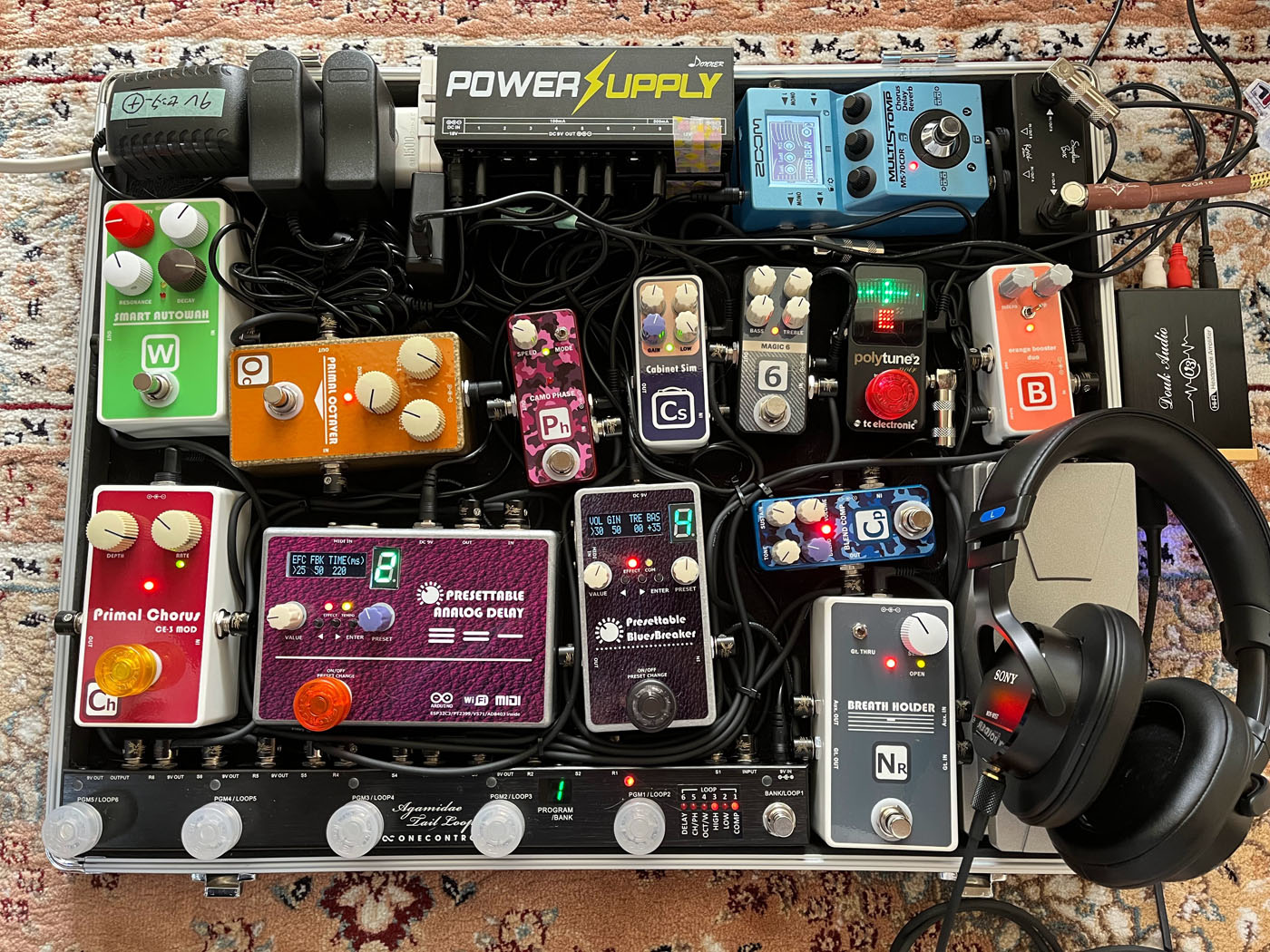
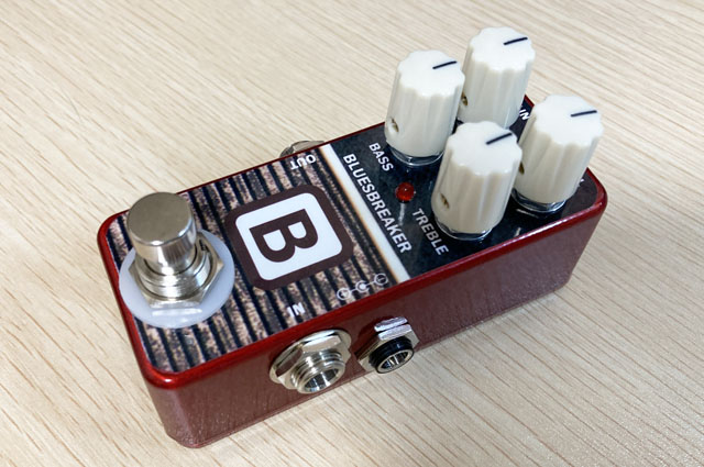 Last time, I used an Arduino-programmable ultra-compact microcomputer board "XIAO ESP32C" for IoT to make my own analog delay that can control presets via MIDI/WiFi. Since the footswitch can instantly change the delay time and feedback, the range of pedalboard coverage has been greatly expanded.
Another effect pedal that I would like to add a preset function to is an overdrive/distortion pedal. I often use my own "BB-Preamp" and "Janray", but when I change the guitar such as Stratocaster or Les Paul, or when the song changes from Smooth Jazz, Rock, Pop, etc., I always adjust the knobs.
Therefore, I made my own presettable pedal by modifying the "BB-Briamp", which has a wide range of tone control and gain adjustment.
MCU controller device
I used the same microcontroller device as the previous AnalogDelay. The XIAO ESP32C ultra-compact microcomputer board for IoT is about the size of a coin, but you can easily use WiFi/MIDI with just this.
All UI related things such as buttons, knobs, LCDs and LEDs are implemented using serial connections.
LCD Display: Connect using I2C on ESP32C3
Button, rotary encoder input: Input via HC165 (parallel to serial conversion)
LED, relay, digital pot: Digital pot and two HC595 (serial to parallel conversion) connected in series
Details of the controller device can be found on the page linked below.
Digital potentiometer
Operating voltage
"BB-Preamp" has four knobs: VOLUME, GAIN, TREBLE, and BASS. Each has a potentiometer (variable resistance) of 50kΩ to 500kΩ. A digital potentiometer can be used to change these resistance values with a microcontroller.
The last time I built my own presettable AnalogDelay, I used an Analog Devices AD8403. It contains four variable resistors and can be controlled by a 3-wire serial interface. However, since this device has a 5V supply voltage, the voltage applied to the variable resistor is also in the range of 0 to 5V. AnalogDelay was able to work in this range.
However, the BB-Preamp's potentiometer changes the tone control and feedback resistance of the op amp, and requires a range of 5V or more. The BB-Preamp has a 12dB gain amplifier after the overdrive (range of about ±0.8V) by diode clipping in the first stage, and the range is more than ±3.5V. The circuit makes full use of the power supply voltage of 9V (±4.5V) to drive a guitar amplifier directly.
Therefore, a digital potentiometer that can handle a range of 9V or higher is required.
"AD5263" from Analog Devices
This time, I chose "AD5263" from Analog Devices. Four variable resistors are built in and can handle ranges up to 15V. The resistance value changes linearly in 8bit/256 steps. Since it can be controlled with the same serial control as the previous "AD8403", I was able to use the previous software.
However, since all four resistors inside the AD5263 have the same resistance value, I chose the version with the same resistance value as the 50kΩ used in the tone control section of the BB-Preamp. I adjusted the circuit constants for the overdrive GAIN (original 500kΩ) and output VOLUME (original 100kΩ).
Pedal control software
Software structure
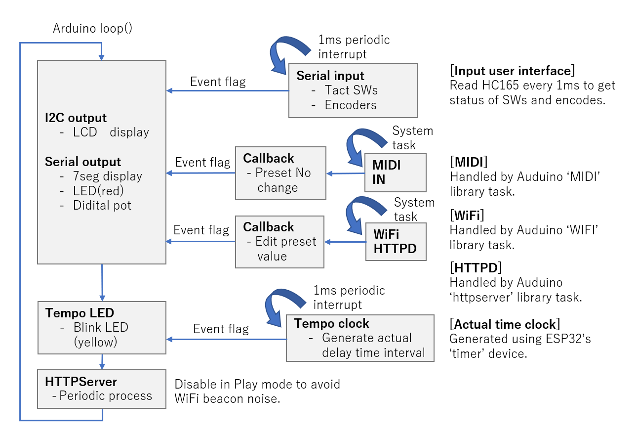
The control of this pedal was programmed in C/C++ using an Arduino. Arduino does not have a multitasking OS, and the main part runs in a polling loop with the function name loop(). The ESP32C3 used has four timer counter functions, and periodic interrupt processing can be easily achieved by simply specifying the interrupt handler function using the Arduino API.
Therefore, I used periodic interrupts (1msec intervals) to capture button and rotary encoder operations. The polling loop is notified with an event flag when a button or encoder changes. Due to the relatively slow interrupt interval, malfunctions due to chattering of buttons and encoders are rare.
Preset switching via MIDI
Using the Arduino library, I made it possible to receive MIDI program change signals and change the preset number using a general switcher with MIDI functions.
Implemented WebServer for editing presets in a web browser
The pedal now has the ability to edit presets in your PC or iPhone's browser, using Arduino's WiFi/WebServer library.
By publishing the pedal's name to the local network using multicast DNS (mDNS), the pedal's internal parameters can be accessed at the address "http://bbp.local".
Details of the pedal control software are explained on the page linked below.
Source code
You can view it on Github. It is complicated because it is packed with functions, but I think it can be partially used.
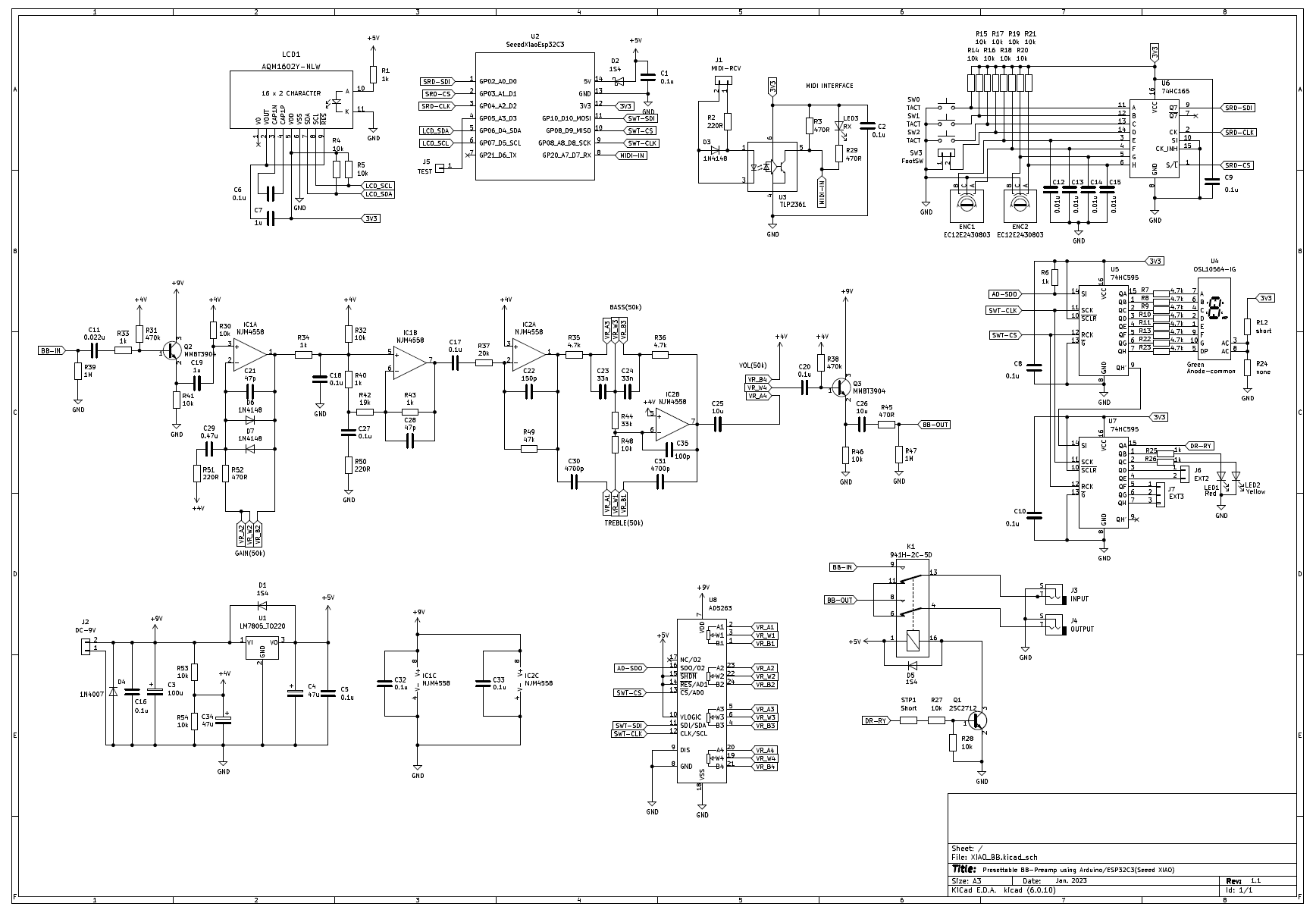
Circuit diagram
A schematic is shown below. A digital potentiometer "AD5263" is connected to the variable resistances of the BB-Preamp circuit.
Design of the controller PCB
Designed with KiCAD and manufactured
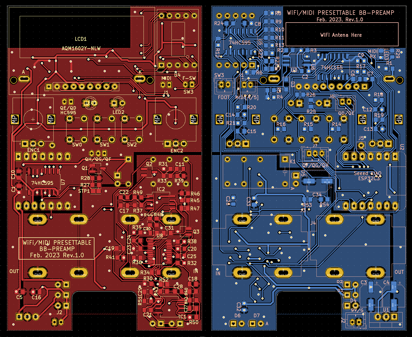
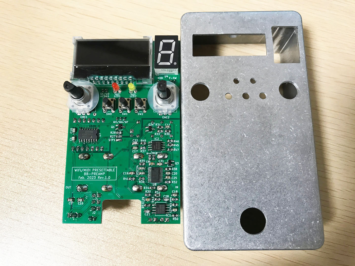
I designed a printed circuit board based on the circuit diagram above. As usual, I designed it with KiCAD and had it made by PCBgogo in China. For the enclosure, I used a compatible product of the "HAMMOND 1590N" that I always use.
This time, the microcomputer part and the analog circuit of the BB-Preamp are on the same board, so I tried to separate them as much as possible and also separate the ground (solid ground) so that digital noise does not interfere with the high-gain analog circuit.
The microcomputer board has a WiFi function, and a WiFi antenna is connected with a very small connector. In order to emit radio waves from the LCD hole of the aluminum enclosure, I stuck an antenna under the LCD. For that reason the ground pattern (solid ground) under the LCD was removed.
KiCad PCB design data
The PCB data created using "KiCad (Windows 64-bit) Version: (6.0.4), release build" is provided. The ZIP file contains the schematic, board design data, and original component data. Please read the terms of use and disclaimer in the attached "readme.pdf" before using this data.
Mounting components on a printed circuit board
Uses surface mount components
The controller board was designed with surface-mounted components, so there are many components on the front and back.
Mount the phone jack on the board
This time, I used "CLIFF" phone jacks that can be mounted on the board. This type of jack can be placed across the width of the enclosure and screwed from the outside of the case.
Operation check
Oscillation of tone control circuit
The BB-Preamp's tone control is an orthodox circuit called NF type audio tone control (BAX type). The cutoff frequency is designed at 1kHz. Many circuits can be found on the internet. It can also be found in TI's TL074 application note.
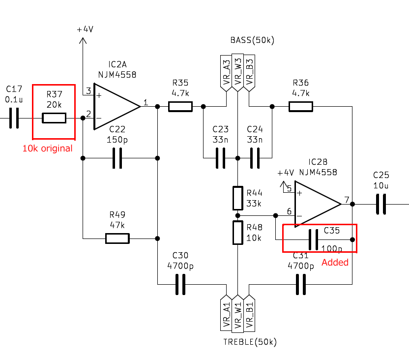
This time, there were no errors in both the circuit diagram and the pattern design. The operation was OK, but the operational amplifier "NJM4558MD" (a low noise surface mount version of JRC's 4558) was oscillating at a high frequency (about 500kHz). Therefore, I added a 100p oscillation stop capacitor to the feedback of the tone control section.
Circuit gain adjustment
The BB-Preamp is designed with a high output level, assuming its use as a preamp that directly drives a guitar amp. Therefore, I think that the VOLUME knob is often used around 9 o'clock on the pedal board.
Therefore, in order to effectively use the range of the digital potentiometer, I lowered the gain of the op-amp in front of the tone control (+12dB in the original circuit) by 6dB. Even with this, the VOLUME knob is at the maximum level around 12 o'clock, but I'll try using this setting.
Microcomputer control system, WiFi works without difficulty
The microcomputer control system is the same circuit as the previous AnalogDelay, so it worked without difficulty.
Frequency response of tone control
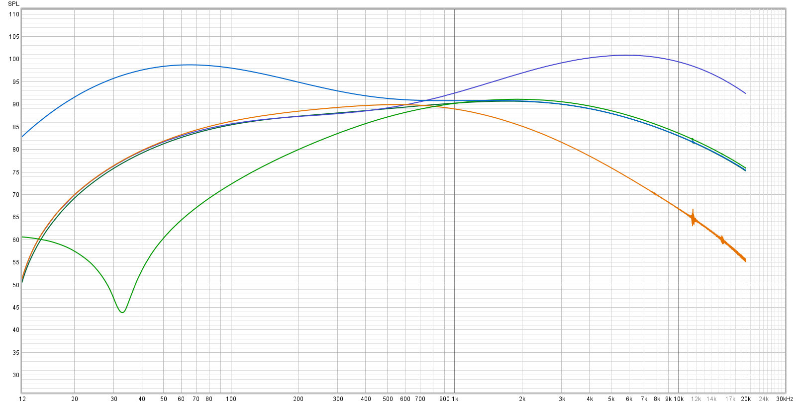
I measured the frequency characteristics of the tone control using the free frequency characteristics measurement software "REW". ±10dB adjustment is possible for both TREBLE and BASS.
Process aluminum die-cast enclosure square holes
Square hole processing is difficult
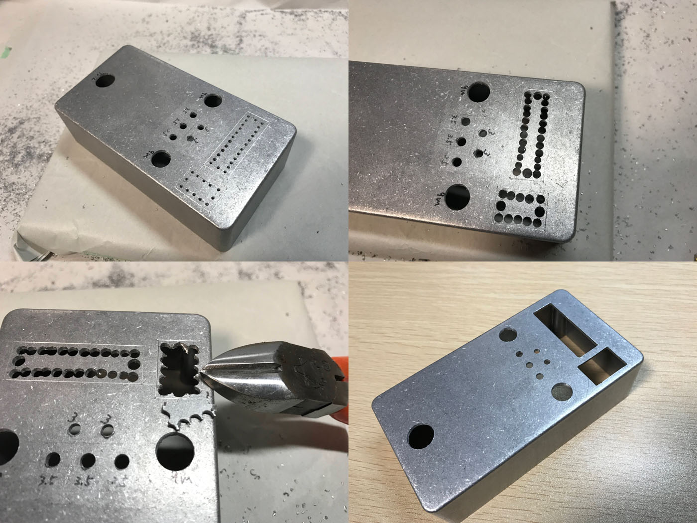
The hardest part of this self-made work was the processing of making a square hole in the die-cast enclosure. Round holes can be easily drilled with a hand drill and reamer. However, square holes can only be cut with a file, and die-cast enclosures are more than 2 mm thick aluminum, so it was not easy.
Built into enclosure and completed
How to fix PCB
The PCB and enclosure are fixed by tightening the nut of the rotary encoder. The wires to the DC jack, MIDI terminal, and footswitch can be easily removed using pin sockets.
Create enclosure label
I created a label using a sticker sheet that can be created with an inkjet printer. I named it "Presetable Blues Breaker" with a leather-like texture that looks like a Marshall amp housing. ("BB" in "BB-Preamp" seems to be the initials of "Blues Breaker".)
Effective preset functionality
By pressing the footswitch (momentary type), you can switch the preset and instantly change the distortion. Since you can change the effect according to the song you are playing, it has a wide range of uses and is extremely effective.
You can edit the preset values inside the pedal from your iPhone's browser using WiFi, so you don't have to squat down and operate the pedal knobs to change the preset values, so I think the operability is perfect.
MIDI presets can be changed, so if you have a MIDI controllable switcher, you can program distortion effect patterns into the switcher's presets.
There are many multi-effectors and digital delays that can be used in this way, but I think analog overdrive/distortion is rare.
Benefits for recording at home
The preset function is useful not only for live performances, but also for recording at home.
If you touch the knob of the effector, the sound will be different from the previously recorded sound. If you punch in/out parts of a take that you don't like, you may not be able to connect the takes well.
Storing knob positions in presets is extremely useful as it allows you to accurately reproduce the previous sound.
Lastly
Many guitarists have multiple overdrive/distortion pedals on their board and use a switcher to change the distortion pattern. I think the ability to change the distortion program via MIDI is very convenient for live performances where you need to change the sound instantly.
I frequently change the knobs on my delay and distortion pedals. I think that these microcomputer control functions will further expand the scope of the pedal board.
Language
Self-made
effect pedals
- Pedals list page
 Tool selection
VEMURAM Jan Ray
Xotic BB preamp
Klon Centaur
 Revived old Chorus
 MXR Envelop Filter
 BBD Analg Delay DM-3
 600ms Analog Delay
 Arduino Analog Delay
 BBD Analg Chorus CE-3
CMOS Octaver OC-2
 Riot using chip parts
 Original design noise gate
 EP & MICRO AMP duo
 Keeley 4 Knob Comp
 MXR Phase 90 MOD
 Keeley Blend Comp
 DM-3 longer delay time
 ISP Decimator V2164


