"MAD PROFESSOR AUTO WAH" MOD self-made report
Self-made Guitar Effect Pedals
Explore the articles to learn more about your favorite effect pedals.
|
Faithfully designed Auto Wah
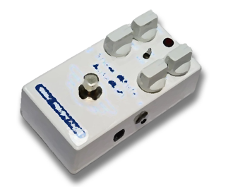 I've made my own MXR Envelop Filter before. I used the circuit diagram posted on the effector self-made article site TONE PAD. The MXR Envelop Filter pedal is so old that it was used in the early 1980s when I was in junior high school.
The MXR pedal has a maniac configuration that uses a CMOS inverter instead of an operational amplifier and an analog switch for the part that changes the cutoff of the LPF. The operating principle is difficult, and I imagine that the constant values of the parts are determined experimentally.
On the other hand, "MAD PROFESSOR AUTO WAH" is a pedal that is faithfully designed according to the basics of electronic circuits.
It uses an operational amplifier and a transconductance amplifier to change the cutoff frequency of the LPF depending on the input level to realize auto wah. This time I would like to make this pedal myself and compare it with my own MXR Envelop Filter.
Circuit and operation outline of MAD PROFESSOR AUTO WAH
The circuit diagram of the pedal was obtained from the overseas site "Revolution".
A transconductance amplifier is a device that can change the conductance (easiness of current flow, reciprocal of resistance) by an external control signal.
MAD PROFESSOR AUTO WAH uses a two-stage transconductance amplifier to create a WAH sound with an LPF that changes the cutoff frequency. The primary LPF is constructed using the output current characteristics (conductance) of the transconductance amplifier and the impedance of the capacitor (C) in the center. It is the same principle as a general primary LPF with one resistor and capacitor.
The LPF cutoff frequency can be changed by controlling the ease of current flow (the reciprocal of resistance) using the function of the transconductance amplifier. Since this conductance can be controlled by an external signal, the WAH-WAH sound is created by following the guitar input by using the level signal (envelope) of the guitar sound.
The feedback resistance of the first-stage transconductance amplifier is variable by the pot (Resonance), which changes the frequency characteristics of the first stage (makes a peak near 2kHz) and has the effect of emphasizing the WAH sound.
This circuit has no tricky elements, and my impression is that it is designed faithfully to the basics of electronic circuits.
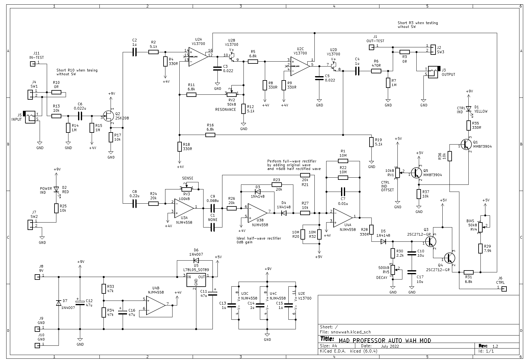
The circuit configuration diagram is shown below. This figure is my own understanding and is not officially published by MAD PROFESSOR.
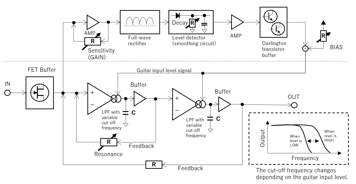
Schematic diagram of the circuit (my understanding)
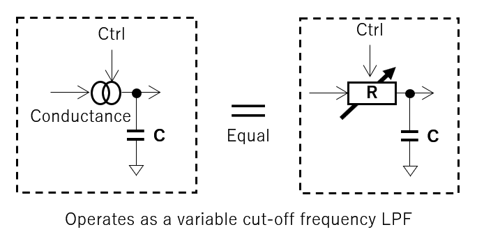
The conductance of the amplifier changes the cutoff frequency of the LPF (my understanding).
Obtaining transconductance amplifier, transistors, and JFET
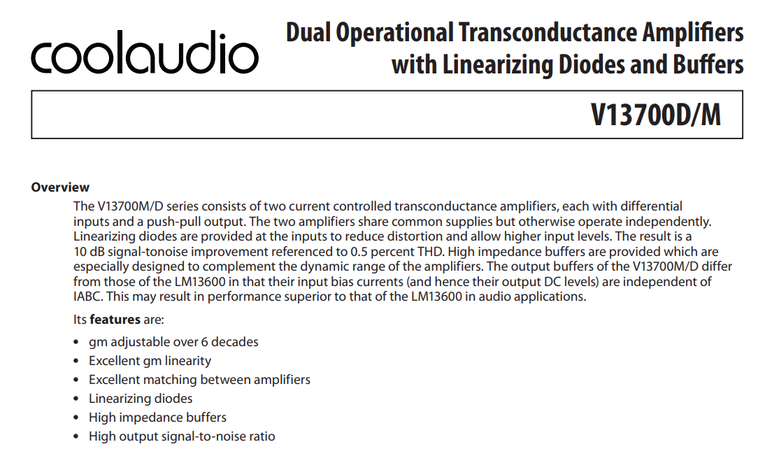 The transconductance amplifier "LM13700" is used for the original circuit. Since this is a special part, it is difficult to obtain it, but fortunately, the Coolaudio surface mount package (SOP16) chip "V13700M" (unit price $ 1) is sold by mail order in Japan. Therefore, I was able to purchase it.
Moreover, in the original circuit, two NPN transistors "BC550" of Darlington connection are used for the level detection circuit. The "BC550" is a Fairchild transistor, but I couldn't find a surface mount package on the Japanese mail order. This chip has a relatively high DC current amplification factor (hFE), but it is a general-purpose transistor for small signals. As an alternative, I decided to use "2SC2712-GR" (a type with high hFE), which is the surface mount version of 2SC1815 that I always use.
Furthermore, "2N5457" is used for the JFET of the input stage in the original circuit. Since this is just a JFET source follower circuit, I decided to use the familiar "2SK208" as an alternative.
Circuit diagram
The circuit diagram I made this time is as follows. Some resistors and capacitors are in parallel or series, because they are not available as surface mount components with just the right constants and are designed with combined resistance / capacitance.
Addition of level indicator
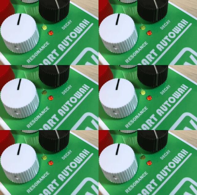 I've added a level indicator to make the "Wah" change visually visible. The guitar input level signal used for controlling the transconductance amplifier is taken out, and the LED is turned on in synchronization with the change of LPF. ("D1, Ctrl IND" part of the circuit diagram)
The drive offset of the LED can be changed with a semi-fixed resistor so that the level at which the LED starts to light can be adjusted.
(Animation GIF image, not actual video)
Circuit diagram of my own auto wah pedal (PDF)
Printed circuit board (PCB) design
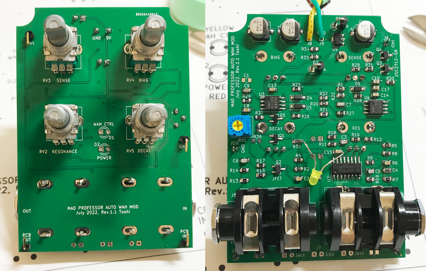
Mounted pot and input / output jack on PCB
This time as well, I tried to design to minimize the wiring inside the enclosure by mounting the pot and input / output jack on the PCB like the products of general effector makers.
The following board mounting pots and jacks are used.
Pots: ALPS RK09L series
Jacks: CLIFF (UK) S4 / MBB / PC-C

If it is difficult to attach the pot directly to the board, or if parts are not available, you can also make it using a universal board and an L-shaped pin header. (Refer to article here.)
Design surface mount PCBs with KiCAD
I made a PCB for surface mount components. I designed a double-sided printed circuit board using "KiCAD". Pots and phone jacks are not available in the KiCAD library, so I create and use footprints (part shape data) myself.
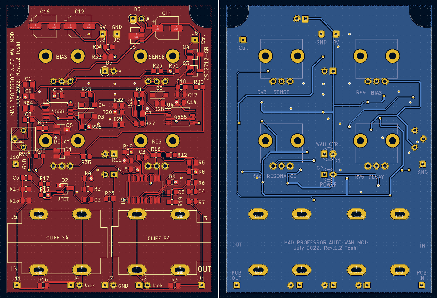
Double-sided trace and silk printing
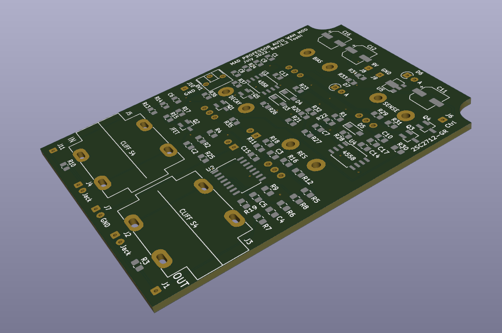
KiCad 3D image display
KiCad PCB design data
The PCB data created using "KiCad (Windows 64-bit) Version: (6.0.4), release build" is provided. The ZIP file contains the schematic, board design data, and original component data. Please read the terms of use and disclaimer in the attached "readme.pdf" before using this data.
KiCad board design data download (ZIP file)
PCB manufactured by "PCBgogo"
This time, I tried using "PCBgogo" which manufactures PCB within "24 hours". When I placed an order, it was actually manufactured and shipped in 24 hours as expected. I tried using "OCS" for this international courier service. This company is a service that provides international home delivery in partnership with the Japanese airline company ANA.
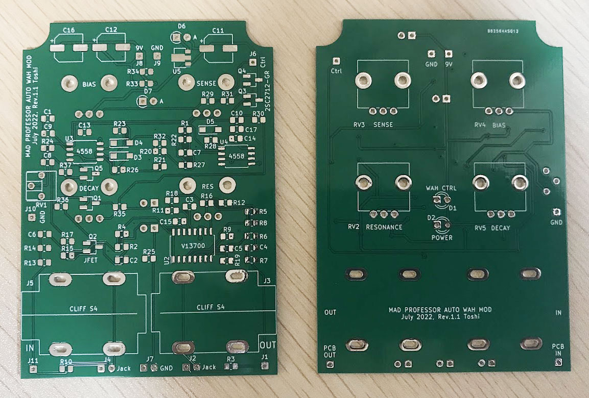
Hand-soldering with chip parts on the board
The surface mount parts are really small, and it is a soldering work using tweezers. I'm used to it, but I think this task is quite difficult for people with old eyes like me. But it's fun work. Since this circuit has a relatively small number of parts, hand soldering was completed in about 2 hours.
The phone jack is a CLIFF board mount type described above and must be soldered to fit the inner width of the enclosure. HAMMOND's enclosure expands in size by about 2mm toward the lid (trapezoidal), so I made the lead hole longer in consideration of the error. The soldering was done after inserting the jack into the board, actually fitting it to the enclosure, and deciding the just position.
Processing of enclosure
This time, pots, LEDs, and phone jacks are all mounted on the board, so it is necessary to drill holes accurately according to the position of the parts. I put the board on the enclosure and marked the hole position so that I could get the position surely. The height of the jack on the side was carefully determined by referring to the dimensional drawing of the pot, the thickness of the board, and the dimensional drawing of the jack.
The enclosure is 1590N1 made by HAMMOND.
After deciding the center position of the parts to be attached, dent the center of the hole with the center punch so as not to shift the hole position, then first make a small hole with a 1.2 mm drill around the dent, 1.5 mm, 2 mm , 2.5mm, 3mm ... 6mm drills gradually widened the holes. 6mm or more is widened with a hand-type taper reamer.
The LEDs were soldered after making a hole in the enclosure. First, I passed the LED lead through the board, temporarily fixed the pot and jack to the enclosure, made the LED head come out from the hole in the enclosure, checked the height of the LED, and then soldered it.
Circuit board operation check
The operation was confirmed by using the free software (WaveGene, Japanese) of the PC and outputting a sine wave from the audio interface (Steinburg UR22mkII) used for recording at home.
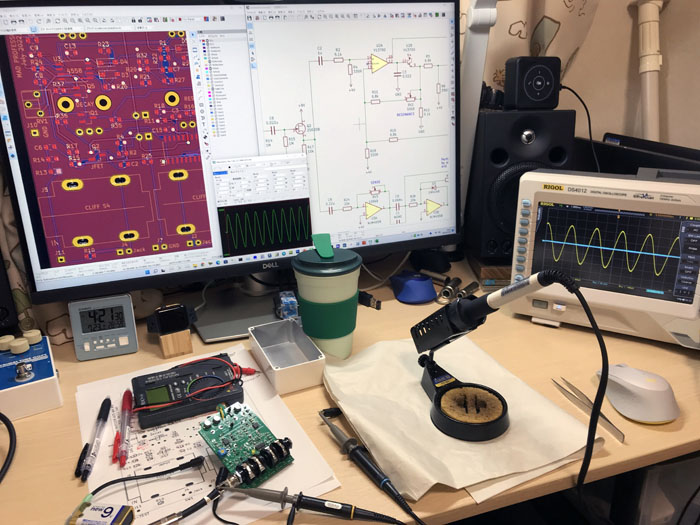
The sound was output in one shot and worked fine, but unfortunately the added LED indicator did not light up well. As a result of tracing the cause with an oscilloscope, the signal extraction position that drives the LED was incorrect. I should have used the buffer output of the level signal of the Darlington transistor buffer, but I took it out from a different place.
After fixing this mistake on the printed circuit board (cutting the pattern and adding the green wire in the photo), it worked as expected.
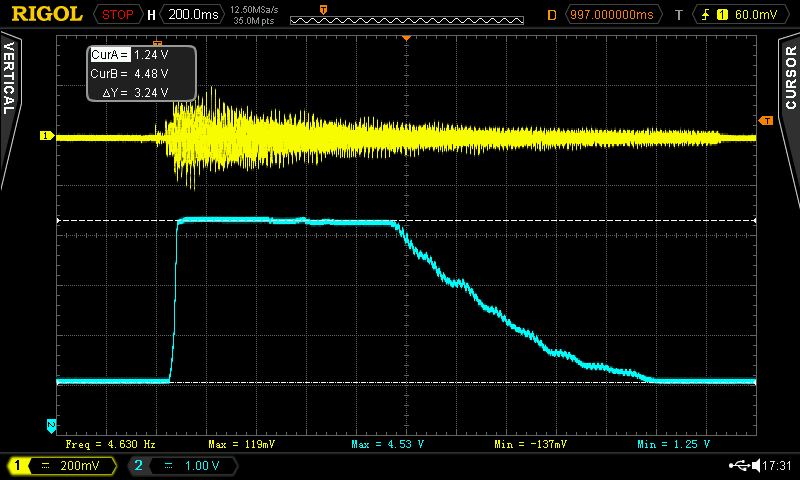
State of change of level signal
This is how the level signal (Ctrl) changes when I play the guitar chord. When the level signal is high, the tone changes to "Wa-" of "Wah", and when the level is low, the tone changes to "-h" of "Wah".
Change in cutoff frequency
I measured the change in the cutoff frequency that makes the "Wah" sound. The free software "REW (Room EQ Wizard)" is used for the measurement.
The graph below compares the maximum / minimum cutoff frequency of the LPF by "SENSITIVITY" that adjusts the input sensitivity. In addition, the change due to "RESONANCE" is also shown.
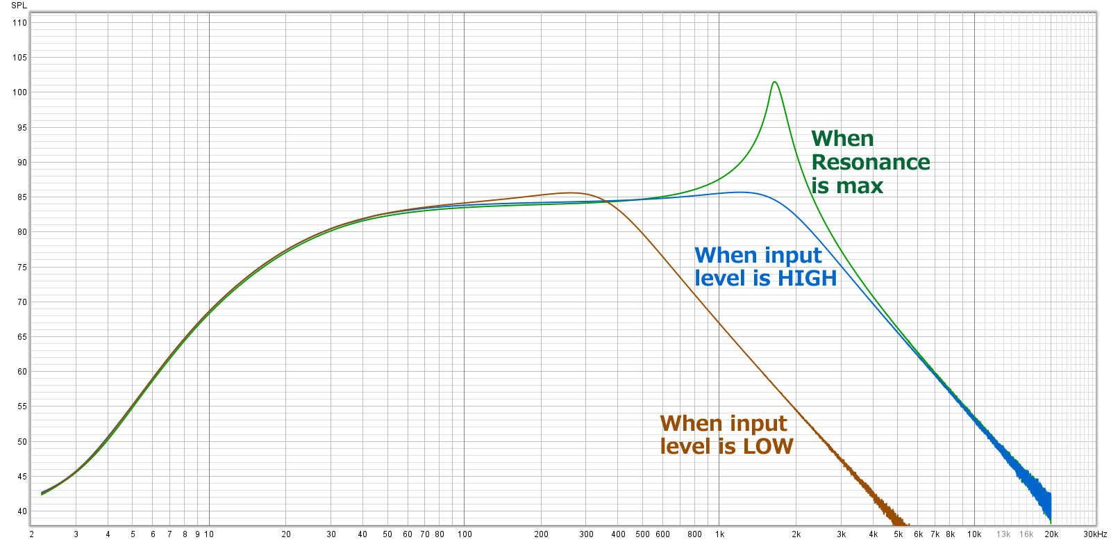
Characteristics of self-made MAD PROFESSOR AUTO WAH
(LPF cutoff changes in the range of 400Hz to 2kHz)
Comparison with MXR Envelop Filter
Similarly, I also measured the characteristics of the MXR Envelop Filter that I made in the past. The frequency response changes are almost the same, but the MXR Envelop Filter has a higher cutoff frequency.
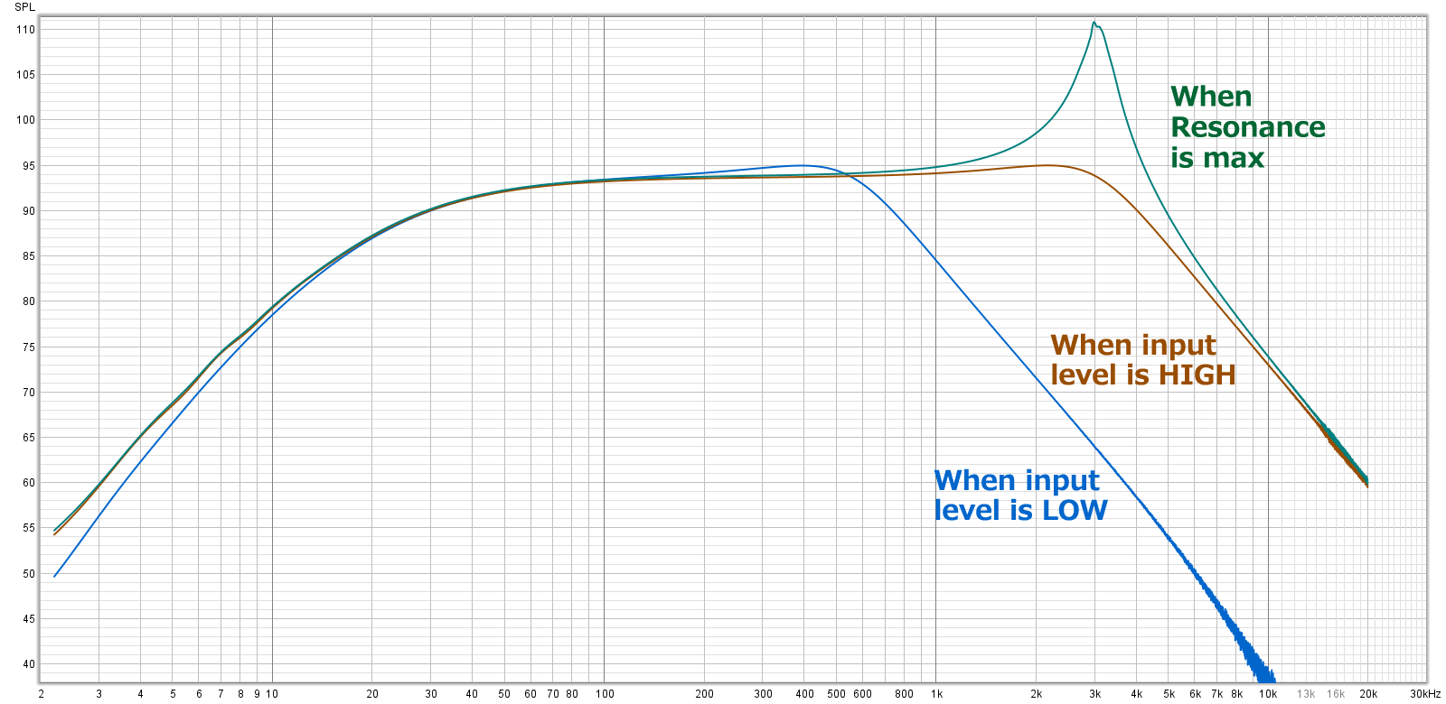
Characteristics of my own MXR Envelop Filter
(LPF cutoff changes in the range of 600Hz to 3kHz)
Comparison of both sounds
This time, "MAD PROFESSOR AUTO WAH" and "MXR Envelop Filter" have similar changes, but "MXR Envelop Filter" sounds more flashy. Also, the sensitivity to picking is higher with the "MXR Envelop Filter", which makes it easier to change when playing a single note.
For both pedals, it may be difficult to notice the wah effect unless the resonance is raised moderately.
As for the sound quality, "MAD PROFESSOR AUTO WAH" sounds more straightforward, but "MXR Envelop Filter" sounds a little distorted. I think that "MAD PROFESSOR AUTO WAH" is more suitable for solo playing, and "MXR Envelop Filter" is more suitable for sound effects.
For changes in sound, the "MXR Envelop Filter" has an Attack adjustment. Since the time from picking until the wah opens can be changed, I think it's easier to change the sound. However, both are difficult to adjust sensitivity and sensitive to picking, so it may be difficult to use in a show.
Sound sample
The recording environment is:
Fender Stratcaster (Mid pickup, single) -> Self-made MAD PROFESSOR AUTO WAH -> Self-made analog cabinet simulator -> UR22mkII -> DAW (Studio One)
![]() Chord and single note rhythm (MP3)
Chord and single note rhythm (MP3)
Below is a sample of the difference due to sensitivity adjustment (Sensitivity).
Gibson Les Paul (Front pickup) -> Self-made MAD PROFESSOR AUTO WAH -> Self-made analog cabinet simulator -> UR22mkII -> DAW (Studio One)
![]() Chord melody (MP3), First half - sensitivity large, Second half - sensitivity small
Chord melody (MP3), First half - sensitivity large, Second half - sensitivity small
Completion of "SMART AUTO WAH"
I wanted to finish it like a commercial product, so I named it "SMART AUTOWAH" and put a sticker on the top of the enclosure. I printed a design image made with PowerPoint on sticker paper with an inkjet printer and cut it out. Holes such as pots are cut out according to the holes after sticking.
The colors of the knobs are different, but there is no particular meaning. This is the result of adding the knob that was left over. :-)
Modified to be able to adjust ATTACK TIME
The "MXR Envelop Filter" has an Attack adjustment. However, this "MAD PROFESSOR AUTO WAH" does not have an Attack adjustment, but instead has a "Decay" adjustment. The Attack Time of "MAD PROFESSOR AUTO WAH" is close to 0, and the tone follows quickly when the strings are picked.
I think it's easier to change the sound if the Wah filter opens slowly after picking. I don't need Decay to slow down and only use it at MIN.
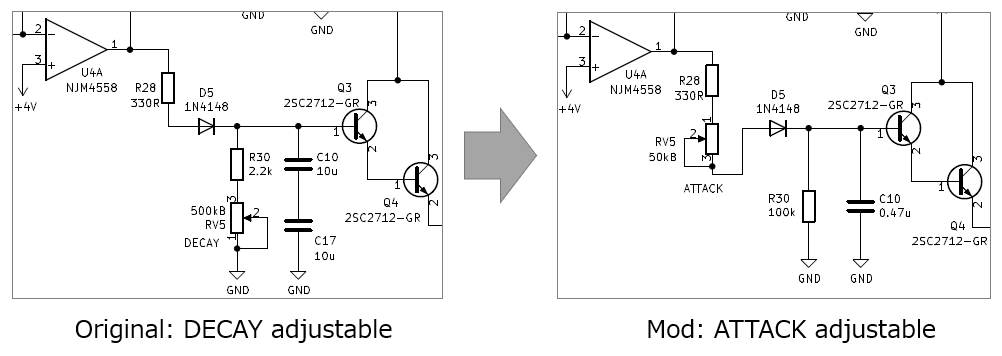
Therefore, I tried to modify the DECAY adjustment to ATTACK adjustment.
Below is the modified circuit. The pot for DECAY of 500kΩ is changed for ATTACK of 50kΩ, and the constant of CR is adjusted.
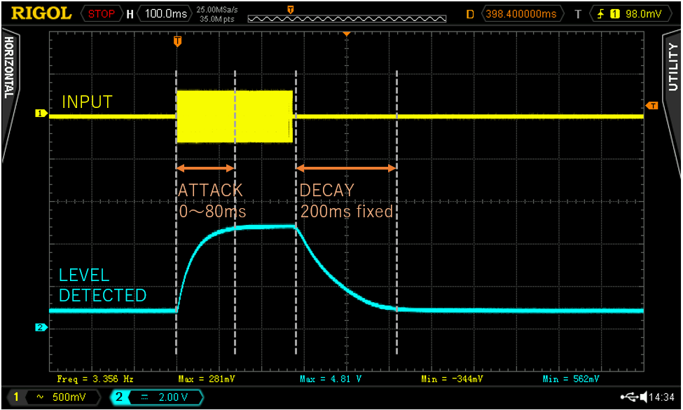
With this modification, DECAY is fixed at about 200ms, but ATTACK can be changed from 0ms to 80ms.
When ATTACK is 0ms, you will hear "WA-H". And when ATTACK is slowed down, it sounds like "H-WA-H" as "H" is added at the top.
Language
Self-made
effect pedals
- Pedals list page
 Tool selection
VEMURAM Jan Ray
Xotic BB preamp
Klon Centaur
 Revived old Chorus
 MXR Envelop Filter
 BBD Analg Delay DM-3
 600ms Analog Delay
 Arduino Analog Delay
 BBD Analg Chorus CE-3
CMOS Octaver OC-2
 Riot using chip parts
 Original design noise gate
 EP & MICRO AMP duo
 Keeley 4 Knob Comp
 MXR Phase 90 MOD
 Keeley Blend Comp
 DM-3 longer delay time
 ISP Decimator V2164


